
Heat exchanger assembly

a technology of heat exchangers and components, applied in refrigeration and liquidation, lighting and heating apparatus, refrigeration machines, etc., can solve the problems of reducing the overall heat exchange performance of the evaporator, affecting the efficiency of the evaporator, and the proportion of the heat exchanger, so as to reduce the complexity of the assembly, reduce the cost, and the effect of tremendous flexibility

Inactive Publication Date: 2008-01-31
DELPHI TECH INC
View PDF8 Cites 30 Cited by
  • Summary
  • Abstract
  • Description
  • Claims
  • Application Information

AI Technical Summary

Benefits of technology

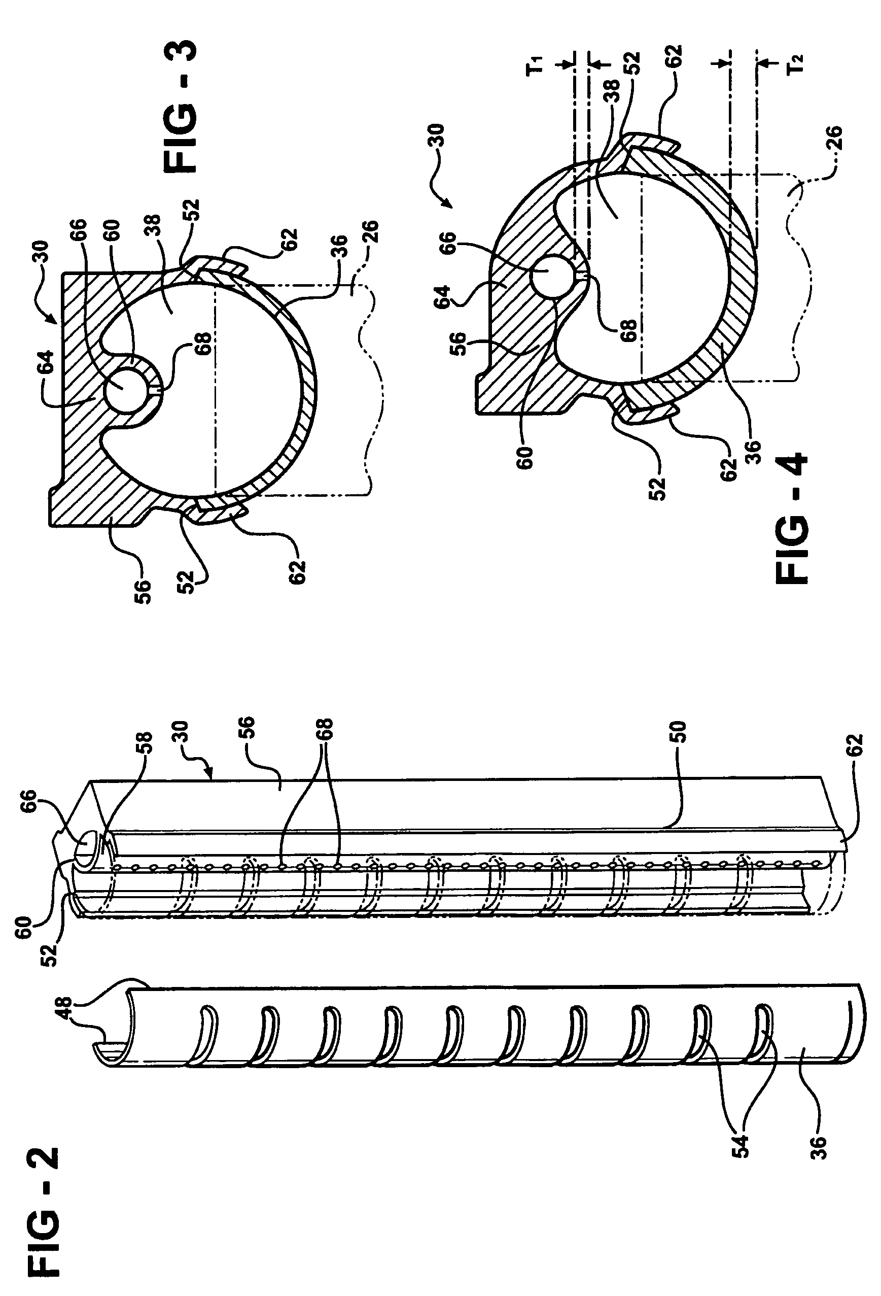
The invention is a heat exchanger assembly with a tank and a header, which are connected by flow tubes to allow refrigerant to pass through. The tank has a distribution chamber inside it with a plurality of openings. The assembly process involves extruding the tank, cutting it to length, and joining it with the header and end cap. The invention simplifies the assembly process and allows for flexibility in creating the openings. The separate tank and header make it cost-effective to produce the header with braze cladding for joining with the tank and flow tubes.

Problems solved by technology

A difficulty arises because the flow characteristics of the refrigerant vary depending on the phase, that is, whether the refrigerant is a gas, liquid, or combination.
When there is poor refrigerant distribution and circulation, some sections of the heat exchanger assembly can be flooded with refrigerant and some can be starved, resulting in unequal heat transfer between portions of the heat exchanger and can cause icing or frosting of portions of the heat exchanger, further diminishing performance.
The largest problems exist when the heat exchanger assembly is operating as an evaporator in order to absorb heat.
Separation of the phases adds to the already present distribution problem within the passes, which further decreases overall heat exchange performance of the evaporator.
Manufacturing costs, particularly assembly costs, can be high because of the number of components, and the precision with which they must be installed to ensure proper alignment.
Conversely, producing single integrated manifolds can present a lack of flexibility in selecting materials and limit manufacturing access to the interior of the manifold.
The distribution tube is a separate component joined to the manifold by welding, and thus the problems related to assembly costs and the difficulty of positive placement of the distribution tube are not addressed.
Further, the shape and configuration of the resulting distribution chamber is limited.

Method used


Image

  • Heat exchanger assembly
  • Heat exchanger assembly
  • Heat exchanger assembly

Examples


Embodiment Construction

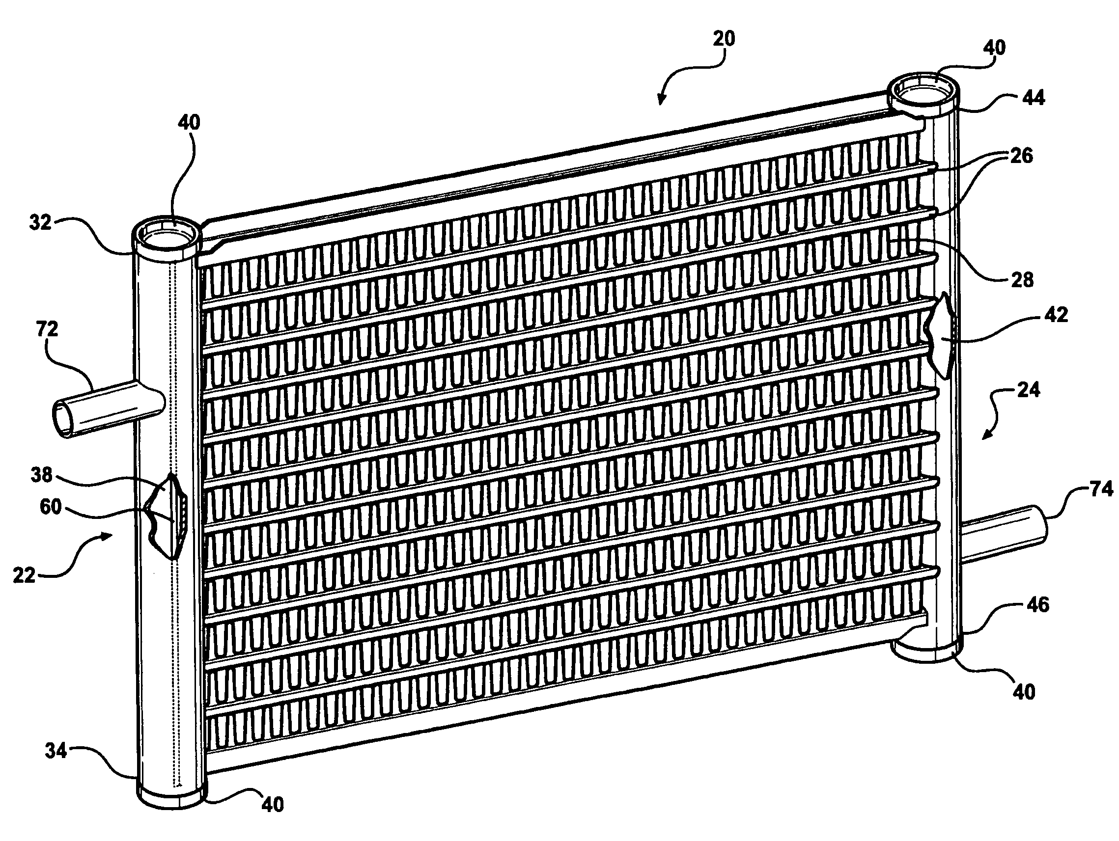
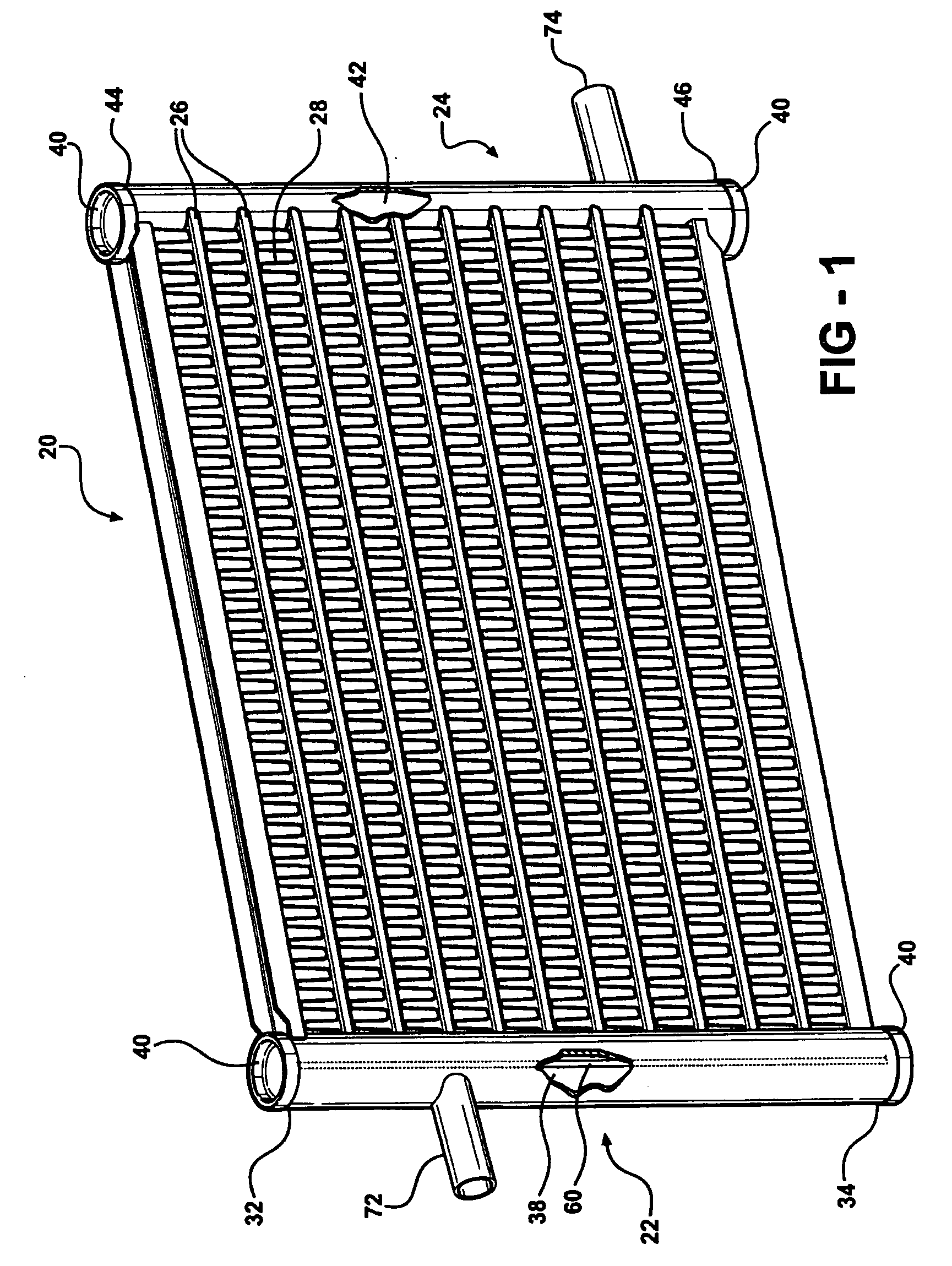
[0031]Referring to the Figures, wherein like numerals indicate corresponding parts throughout the several views, a heat exchanger assembly is generally shown at 20 in FIG. 1. The heat exchanger assembly 20 includes a first manifold 22, a second manifold 24, and a plurality of flow tubes 26 fluidly connecting the manifolds 22, 24. A plurality of heat conducting structures are disposed between the plurality of flow tubes 26, which are illustrated as fins 28. As is known to those skilled in the art, the first manifold 22 may be commonly referred to as an inlet manifold, therefore performing an inlet function, and the second manifold 24 may be commonly referred to as an outlet manifold, therefore performing an outlet function, however, the opposite could be true. Reference to the first and second manifolds 22, 24 is interchangeable in the description of the subject invention.

[0032]The first manifold 22 includes a tank 30 having a length, a first end 32 and a second end 34, and a header ...


PUM


Abstract

A heat exchanger assembly has a first manifold, a second manifold in spaced and substantially parallel relationship with the first manifold and a plurality of flow tubes fluidly connecting the manifolds for passing refrigerant between the manifolds. The first manifold includes a header and tank which are joined by their longitudinal edges to form a cavity. The tank is extruded and has an outer wall and an inner partition wall with a plurality of apertures which define a distribution chamber within the cavity. The distribution chamber is fluidly connected to the cavity. A method of manufacturing a manifold generally includes the steps of extruding the tank, cutting the tank to a predetermined length, forming a plurality of apertures in the inner partition wall, forming a plurality of openings in the header, joining the tank and the header, and joining the end cap to the tank and header.

Description

BACKGROUND OF THE INVENTION[0001]1. Field of the Invention[0002]The present invention relates to a heat exchanger assembly and method of manufacturing a manifold.[0003]2. Description of the Prior Art[0004]Heat exchanger assemblies are widely used in a variety of applications, and can be either single mode or dual mode, depending on whether functioning solely as either a condenser or an evaporator, or if functioning as both. The heat exchanger assemblies generally include a pair of manifolds fluidly connected by a plurality of flow tubes. Heat conducting structures, such as fins, are generally disposed between the flow tubes to add surface area to the heat exchanger assembly for further aiding in heat transfer to or from ambient air passing over the flow tubes. Refrigerant enters the heat exchanger assembly through one or more ports which are connected to one or both manifolds. Refrigerant passes through the heat exchanger assembly and is exited through one or more ports connected to...

Claims


Application Information

Patent Timeline
Patent Type & Authority Applications(United States)
IPC IPC(8): F28F9/02
CPCF25B39/022F28D2021/007F28D2021/0071F28F2255/16F28F9/0273F28F2220/00F28F9/0224
Inventor BEAMER, HENRY EARLFULLER, CHRISTOPHER ALFREDRUNK, ROBERT MICHAELWINTERSTEEN, DOUGLAS CHARLES
Owner DELPHI TECH INC
Learn More