Multiple beam charged particle optical system

a particle and optical system technology, applied in the field of microlens arrays, can solve the problems of low throughput, coulomb blur in conventional single beam systems, and limited system throughput, and achieve the effect of small aperture lens strength and field curvature correction

Active Publication Date: 2008-01-31
ASML NETHERLANDS BV
View PDF17 Cites 27 Cited by
  • Summary
  • Abstract
  • Description
  • Claims
  • Application Information

AI Technical Summary

Benefits of technology

[0026] A micro-lens array with limited lens field: in case of a two-electrode lens array, the separation between two electrodes is less than a few tens of microns, and the lens bore diameter, in case of an elliptical shape, the smallest diameter, is smaller than the thickness of the lens electrode; in case of aperture lens array, the lens diameter is smaller than the thickness of the electrodes. In this way, the third order aberrations, especially coma and astigmatism, will be minimized for off-axial beamlets.
[0027] The first order field curvature due to a longer objective distance for off-axial beamlets is compensated by increasing the radius of the off-axial lens holes, so that each lens of the lens array focuses a beamlet at the same image plane
[0028] For the aperture lens array, alternatively, the field curvature can be corrected by adding three macro electrodes facing the lens aperture, with the potential of the first macro electrode the same or higher as that of the aperture lens array. This configuration leads to a curved equal-potential plane in front of the aperture lens array. The curvature of the equal-potential plane leads to a smaller aperture lens strength for the off-axial lenses than that of the central lens, and in this way, the field curvature can be corrected.

Problems solved by technology

Conventional single beam systems suffer from coulomb blur and low throughput.
However, the astigmatism becomes dominant with increasing incident angle and eventually restricts the maximum incident angle to less than 30 mrad, thus the throughput of the system is limited.
The throughput of the system is also restricted due to a small filling factor of the lens that is allowed.
In this solution, the curvature of the lens plate leads to undesired engineering challenges.
Also, drawbacks include that the image plane for all the beamlets is present in a concaved surface with respect to the source.
Further, a difficulty exists in the alignment between the lens array and a “spatial filter”, in fact the current limiting aperture structure, which in this publication is taught to be on a planar surface.

Method used


Image

  • Multiple beam charged particle optical system
  • Multiple beam charged particle optical system
  • Multiple beam charged particle optical system

Examples


Embodiment Construction

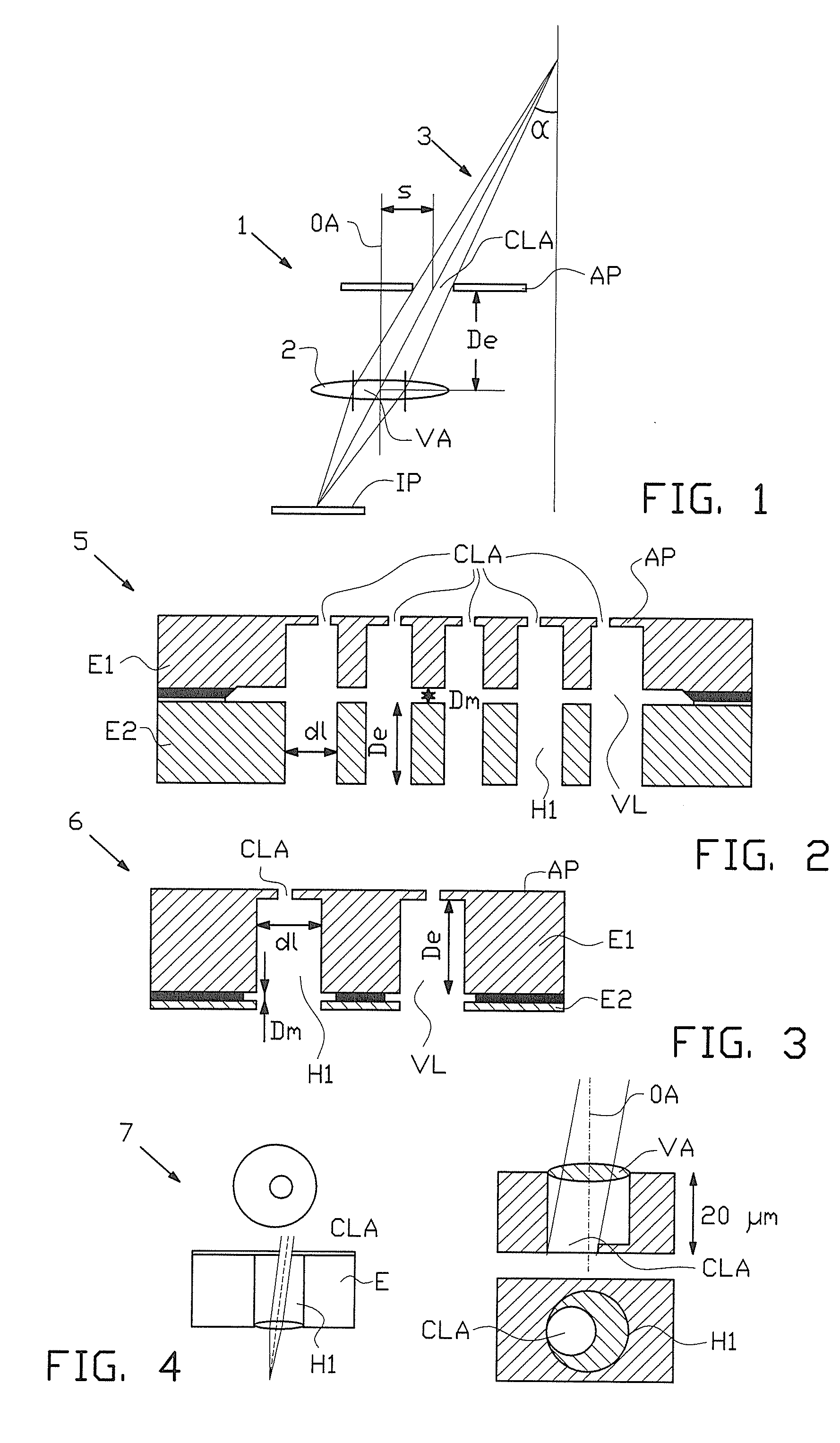
[0042]FIG. 1 shows an alignment of a current limiting aperture CLA, normally part of an array of such apertures CLA and included in an aperture plate AP, and a lens 2. The current limiting aperture CLA of the lens is in such a position, that for a beam 3, such as a charged particle beam, with a certain incident angle α, the virtual aperture VA is located in a centre part of the lens 2, and symmetrical along the optical axis OA of the lens. Here, the middle, i.e. centre of the lens means the geometry centre of the lens. In case of a two electrode lens, the middle of the lens is at the middle of two electrodes and the in case of three electrode lens, the middle of the lens is at the middle of the central electrode, and in case of an aperture lens, the middle of the lens is at the end plane of the aperture. The image further shows an image plane IP.

[0043] In FIG. 2 and FIG. 3, two examples of two-electrode lens arrays are presented in the form of lens structures 5, 6, in short also de...


PUM


Abstract

The invention relates to a multiple beam charged particle optical system, comprising an electrostatic lens structure with at least one electrode, provided with apertures, wherein the effective size of a lens field effected by said electrode at a said aperture is made ultimately small. The system may comprise a diverging charged particle beam part, in which the lens structure is included. The physical dimension of the lens is made ultimately small, in particular smaller than one mm, more in particular less than a few tens of microns. In further elaboration, a lens is combined with a current limiting aperture, aligned such relative to a lens of said structure, that a virtual aperture effected by said current limiting aperture in said lens is situated in an optimum position with respect to minimizing aberrations total.

Description

[0001] The present patent application is a non-provisional application claiming the priority of U.S. Provisional Application No. 60 / 833,394, filed Jul. 25, 2006.BACKGROUND OF THE INVENTION [0002] The present invention relates to a charged particle beam system such as an electron beam exposure system, scanning and non-scanning electron microscopes, and the like. FIELD OF THE INVENTION [0003] The current invention presents a microlens array for generating a plurality of focused beamlets or focusing beams with different incident angles in a charged particle beam exposure or imaging apparatus with zero field curvature, minimized geometrical aberrations such as coma and astigmatism, comprising a current limiting aperture, generating a plurality of charged particle beamlets, a lens array aligned with the current limiting aperture, for focusing all the beamlets into a flat image plane. It solves the problem of how to generate a plurality of focussed beamlets with a minimum of aberrations i...

Claims


Application Information

Patent Timeline
Patent Type & Authority Applications(United States)
IPC IPC(8): G21K1/08
CPCH01J37/12H01J37/153H01J2237/317H01J2237/1205H01J2237/121H01J2237/04924
Inventor KRUIT, PIETERZHANG, YANXIAVAN BRUGGEN, MARTIJN J.STEENBRINK, STIJN WILLEM HERMAN KAREL
Owner ASML NETHERLANDS BV
Why Eureka
Try Eureka