Eureka AIR delivers breakthrough ideas for toughest innovation challenges, trusted by R&D personnel around the world.

Low mass six degree of freedom stage for lithography tools

Inactive Publication Date: 2008-01-31
NIKON CORP
View PDF32 Cites 11 Cited by
  • Summary
  • Abstract
  • Description
  • Claims
  • Application Information

AI Technical Summary

Benefits of technology

[0010] A reticle or wafer stage mover with six degrees of freedom, a low mass coarse stage, and the ability to move an object in a scanning direction in a lithography tool, is disclosed. The mover includes a coarse stage and a fine stage configured to support the object and supported by the coarse stage. A set of actuators is provided to move the fine stage in six degrees of freedom. All of the actuators contribute to accelerating the object and the fine stage in the scanning direction. With all the actuators generating the necessary force to move the fine stage, a single large actuator to push the fine stage in the scanning direction is eliminated. The size or mass of the coarse stage is therefore reduced. All of the actuators are also capable of generating a second force in either the X or Z directions. The actuators therefore also enable the fine stage and the object it supports to be positioned in six degrees of freedom, as well as moved in the scanning direction.

Problems solved by technology

The issue with this type of stage is its movement is limited, and is unable to move in the vertical (Z, θx and θy) degrees of freedom.
Since the aforementioned single stage does not have six degrees of freedom, its use in future lithography tools may be limited.
The larger the mass, the more difficult it will become to accelerate the coarse stage.
Consequently, the mass of this stage design has made it a limiting factor in increasing the rate of acceleration, and hence throughput, of future lithography tools.

Method used


Image

  • Low mass six degree of freedom stage for lithography tools
  • Low mass six degree of freedom stage for lithography tools
  • Low mass six degree of freedom stage for lithography tools

Examples


Embodiment Construction

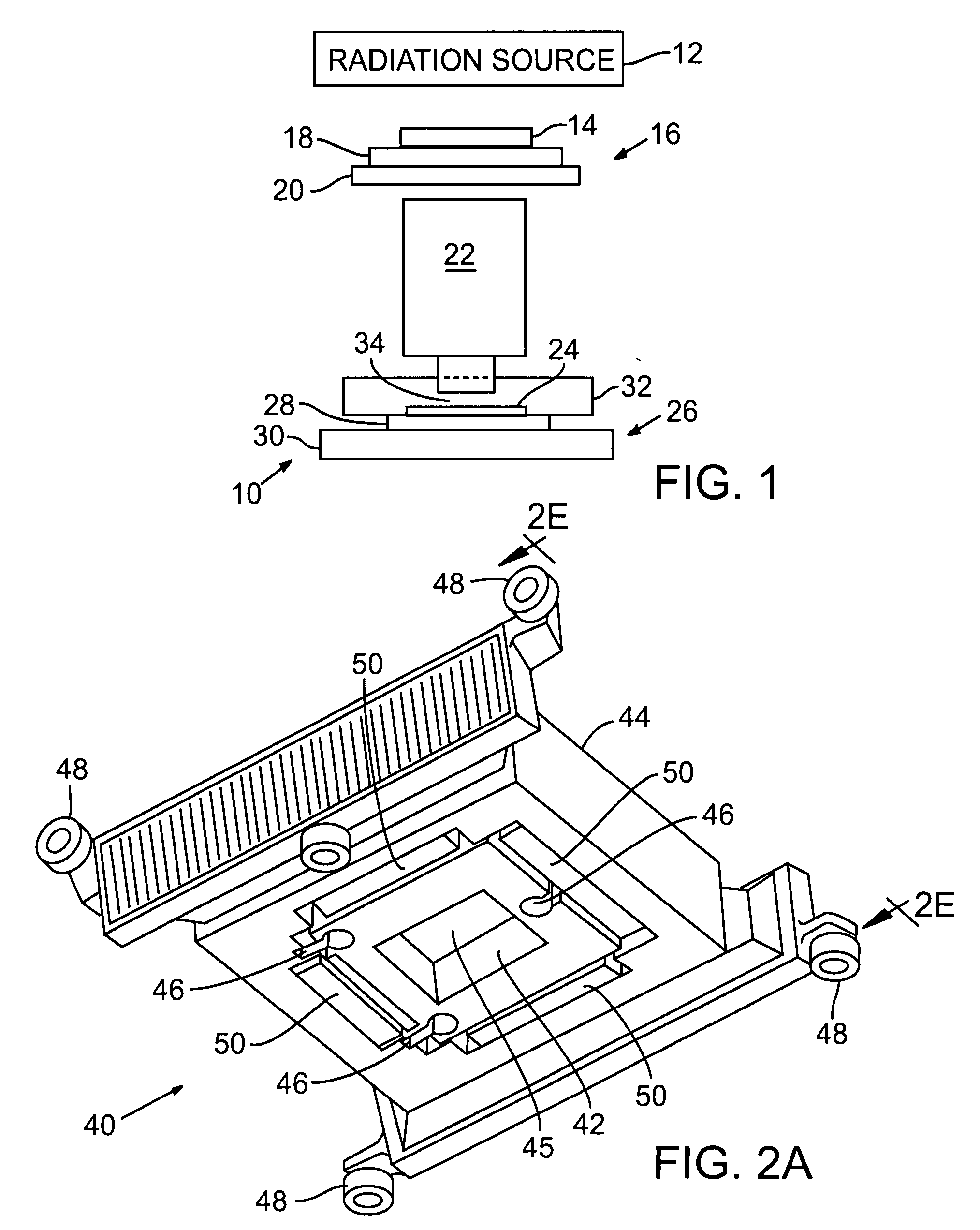
[0017] Referring to FIG. 1, a lithography tool or apparatus is shown. The apparatus 10 includes a radiation source 12, a patterning element 14, such as a reticle, which defines a pattern, a first mover 16 including a fine stage 18 and a coarse stage 20 to support and position the patterning element 14, and a projection optical system 22 to project radiation from the source 12 through the patterning element 14 onto a wafer 24 for the purpose of patterning the wafer as is well known in the lithography art. The wafer 24 is supported and positioned by a second mover 26 that includes a fine stage 28 and a coarse stage 30. In the embodiment shown, the apparatus 10 is an immersion type lithography tool. As such, the apparatus 10 further includes an immersion element 32, which maintains an immersion fluid (not illustrated) in the gap 34 between the last optical element 36 of the projection optical system 22 and the wafer 24. It should be noted that the embodiment shown is only exemplary. In...


PUM


Abstract

A reticle or wafer stage mover with six degrees of freedom, a low mass coarse stage, and the ability to move an object in a scanning direction in a lithography tool. The mover includes a coarse stage and a fine stage configured to support the object and supported by the coarse stage. A set of actuators is provided to move the fine stage in six degrees of freedom. All of the actuators contribute to accelerating the object and the fine stage in the scanning direction. With all the actuators generating the necessary force to move the fine stage, a single large actuator to push the fine stage in the scanning direction is eliminated. The size or mass of the coarse stage is therefore reduced. All of the actuators are also capable of generating a second force in either the X or Z directions. The actuators therefore also enable the fine stage and the object it supports to be positioned in six degrees of freedom, as well as moved in the scanning direction.

Description

RELATED APPLICATIONS [0001] This application claims priority on Provisional Application Ser. No. 60 / 801,582 filed on May 18, 2006 and entitled “Maglev Reticle Stage: Fine+Coarse / Carrier Stage”, the content of which is incorporated herein by reference for all purposes.BACKGROUND [0002] 1. Field of the Invention [0003] The present invention relates to lithography, and more particularly, to a stage design including a low mass coarse stage that provides support and positions a fine stage capable of movement in six degrees of freedom. [0004] 2. Related Art [0005] A typical lithography tool includes a radiation source, a projection optical system, and a substrate stage to support and move a substrate to be imaged. A radiation-sensitive material, such as resist, is coated onto the substrate surface prior to placement onto the substrate stage. During operation, radiation energy from the radiation source is used to project an image defined by an imaging element through the projection optical...

Claims


Application Information

Patent Timeline
IPC IPC(8): G03B27/58G03B27/62H02K41/00
CPCG03F7/70716H02K2201/18H02K41/03G03F7/70758
Inventor WILLIAMS, MARKPHILLIPS, ALTON
Owner NIKON CORP
Why Eureka
Eureka Blog
Learn More