Optical encoder and collimator lens

a collimator lens and optical encoder technology, applied in the field of optical encoders, can solve the problem of unobtainable favorable interference output, and achieve the effect of high accuracy and favorable interference outpu

Active Publication Date: 2008-01-31
MITUTOYO CORP
View PDF22 Cites 19 Cited by
  • Summary
  • Abstract
  • Description
  • Claims
  • Application Information

AI Technical Summary

Benefits of technology

[0019]According to the present invention, the parallelization degree of light which enters a grating is mitigated, and the second-order and the third-order or high-order diffraction l

Problems solved by technology

In recent years, a light-generating source used as the light source 14 has become small in size and close to an ideal point-light source, interference becomes excessively intense, and as shown in FIG. 2, not only ±first-or

Method used


Image

  • Optical encoder and collimator lens
  • Optical encoder and collimator lens
  • Optical encoder and collimator lens

Examples


embodiment 1

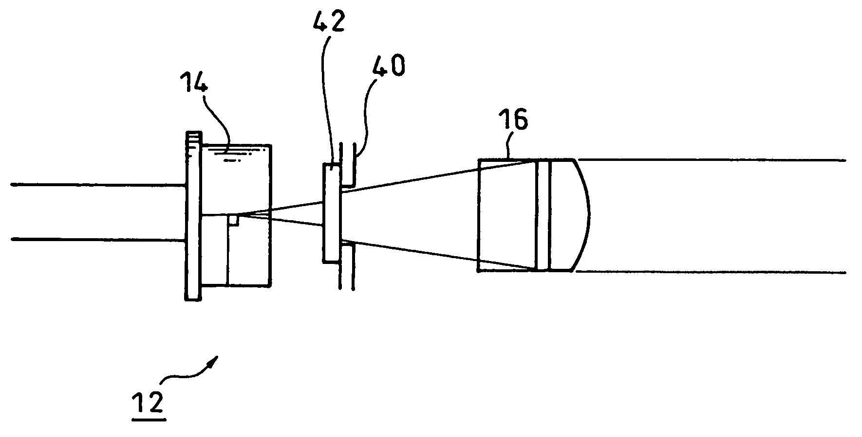
[0031]As shown in FIG. 4, in Embodiment 1 of the present invention, an aperture 40 for preventing stray light is provided between the light source 14 of the light source portion 12 and the collimator lens 16, wherein the aperture 40 is provided with a diffusion plate 42.

[0032]According to the present embodiment, it is possible to prevent the stray light and mitigate the parallelization degree at the same time.

embodiment 2

[0033]Next, a detailed description will be made for Embodiment 2 of the present invention with reference to FIG. 5.

[0034]In the present embodiment, an aperture 40 and a diffusion plate 42 are made integrated and a part of the aperture 40 is used as the diffusion plate 42.

[0035]According to the present embodiment, the constitution is quite simple.

embodiment 3

[0036]Next, a detailed description will be made for Embodiment 3 of the present invention with reference to FIG. 6.

[0037]In the present embodiment, a diffusion plate 42 is provided on the surface of a light source 14 of a collimator lens 16.

[0038]According to the present embodiment, it is not necessary to separately provide the diffusion plate 42. The surface on the light source 14 side of the collimator lens 16 itself may be given as a rough surface and also made as a diffusion surface without the diffusion plate. Further, the surface on the grating side of the collimator lens 16 itself may be made as a diffusion surface.


PUM


Abstract

In an optical encoder which is designed to convert light generated from a light source into parallel light rays by using a collimator lens, thereby allowing the collimated light to radiate to gratings (a first grating, a second grating and a third grating), a diffusion means (a diffusion plate or a diffusion surface) is provided between the light source and the collimator lens to mitigate the parallelization degree of light, thereby weakening the second-order and the third-order or high-order diffraction light. Thereby, even where a light emitting diode (LED) or laser diode (LD) is used as the light source, a favorable interference output can be obtained.

Description

CROSS-REFERENCE TO RELATED APPLICATION[0001]The disclosure of Japanese Patent Application No. 2006-206195 filed on Jul. 28, 2006 including specifications, drawings and claims is incorporated herein by reference in its entirety.BACKGROUND OF THE INVENTION[0002]1. Field of the Invention[0003]The present invention relates to an optical encoder which is designed to convert light generated from a light source into parallel light rays by using a collimator lens, thereby allowing the collimated light to radiate to a grating and also to the collimator lens therefor. In particular, the present invention relates to an optical encoder capable of obtaining a favorable interference output appropriately used in optical encoders such as a linear encoder, a linear gauge and an arc-shaped encoder (a rotary encoder) employing point light sources such as a light emitting diode (LED) and a laser diode (LD) used as a light source, and also to a collimator lens therefor.[0004]2. Description of Related Ar...

Claims


Application Information

Patent Timeline
IPC IPC(8): G01B11/14G02B27/30
CPCG01D5/38
Inventor OTSUKA, TAKANORIKODAMA, KAZUHIKO
Owner MITUTOYO CORP
Why Eureka
Try Eureka