Method and apparatus for bonding dissimilar materials made from metals

a technology of dissimilar materials and methods, applied in the direction of soldering apparatus, manufacturing tools,auxillary welding devices, etc., can solve the problems of corrosive current flow between the dissimilar metals, accelerate corrosion, and occur due to the contact of the dissimilar metals

Active Publication Date: 2008-01-31
NISSAN MOTOR CO LTD
View PDF6 Cites 40 Cited by
  • Summary
  • Abstract
  • Description
  • Claims
  • Application Information

AI Technical Summary

Problems solved by technology

This can accelerate corrosion.
The corrosion due to the contact of the dissimilar metals occurs because there is a voltage difference between these metals, which is caused by a difference in the ionization tendencies of the respective materials.
Thus, corrosive currents flow between the dissimilar metals.

Method used


Image

  • Method and apparatus for bonding dissimilar materials made from metals
  • Method and apparatus for bonding dissimilar materials made from metals
  • Method and apparatus for bonding dissimilar materials made from metals

Examples


first embodiment

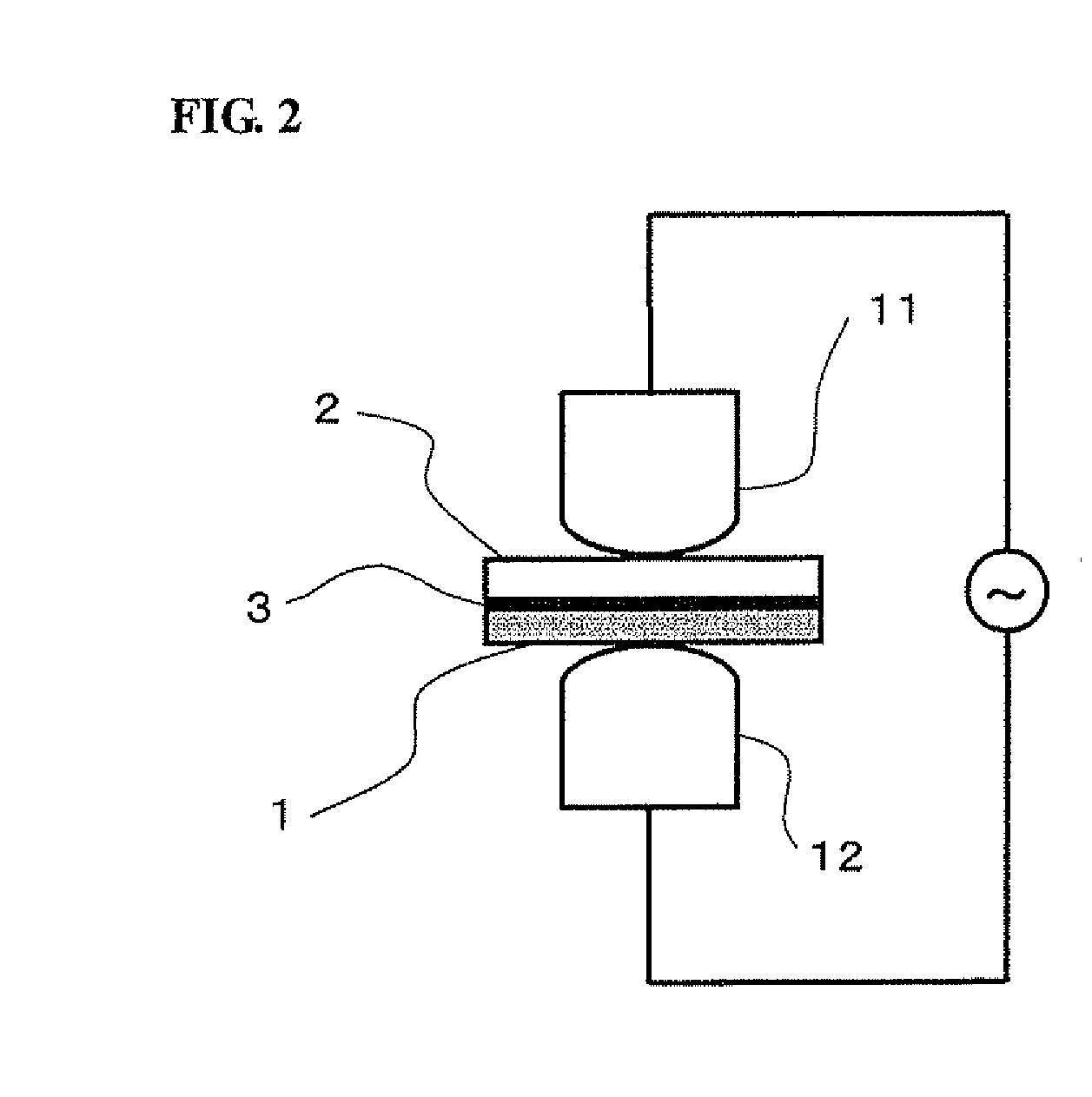
[0076]FIG. 2 illustrates a spot welding device employed in the first embodiment. The zinc-plated steel sheet 1 and the aluminum alloy 2 having the seal material 3 interposed therebetween are welded by pressing and conducting with a pair of welding electrodes 11 and 12 using an alternating current supply device.

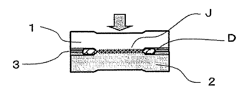
[0077]FIG. 3 illustrates a bonding portion in detail. The zinc-plated layer 1p is formed on the surface. Further, the seal material 3 is interposed between a bonding interface of the zinc-plated steel sheet 1 and the aluminum alloy material 2.

[0078]The spot welding electrodes 11 and 12 include convex surfaces 11a and 12a at their ends so as to easily discharge the seal material 3, an oxide film and a eutectic fused body from the bonding interface, as explained below.

[0079]It is to be understood that both electrodes 11 and 12 do not necessarily have the shape of the end of the electrode. At least one of the electrodes 11 and 12 may have such a shaped end to perform smooth disch...

second embodiment

[0095]In the first embodiment, an example has been illustrated that facilitates a discharge of the seal material from the bonding portion or a reaction product generated during a bonding process using the welding electrodes having the convex surfaces at their ends. Alternatively, the same effects may be obtained when the bending portion having a predetermined curvature is formed on at least one bonding surface of the bonded material. In other words, in the present embodiment, as shown in FIG. 6A, the aluminum alloy material 2 having a bending portion 2a, which is formed in advance by pressing, is overlapped with the zinc-plated steel sheet 1. Further, the seal material 3 is interposed between the aluminum alloy material 2 and the zinc-plated steel sheet 1.

[0096]Additionally, the zinc-plated steel sheet 1 and the aluminum alloy material 2 are interposed between the electrodes 11 and 12. Under such a condition, when the pressing is performed, the seal material 3 is easily discharged f...

third embodiment

[0099]FIG. 7 illustrates an example wherein the bending portion 2b for facilitating the discharging of the seal material is formed as a thick portion on the aluminum alloy material 2. In other words, when the aluminum alloy material 2 is a cast material or an extrusion material, the thick bending portion 2b can be easily formed during a manufacturing process. Further, the seal material 3 as well as the reaction product can be easily discharged from the bonding interface. Therefore, the same effects as the above-mentioned embodiments can be obtained.


PUM

PropertyMeasurementUnit
temperatureaaaaaaaaaa
thicknessaaaaaaaaaa
pressing forceaaaaaaaaaa

Abstract

A method of bonding dissimilar metals, a bonding structure formed by such a method and a bonding apparatus for performing such a method. The resulting bond is capable of preventing corrosion (e.g., electric corrosion) resulting from contact of the dissimilar metals and obtains a dissimilar material joint exhibiting anti-corrosive property and bonding strength at low costs. The method includes overlapping two materials made from dissimilar metals having a seal material interposed therebetween and discharging the seal material from a bonding interface and bonding the two materials in direct contact with each other.

Description

CROSS-REFERENCE TO RELATED APPLICATION[0001]This application claims priority from Japanese Patent Application Serial No. 2006-201861, filed Jul. 25, 2006, which is incorporated herein in its entirety by reference.TECHNICAL FIELD[0002]The invention relates in general to a method for bonding dissimilar materials made from metals with different ionization tendencies, a bonding structure for dissimilar metals formed by using such a method and an apparatus for bonding dissimilar materials made from metals for use in such a method.BACKGROUND[0003]Steel has been widely used in forming a vehicular body. However, in addition to steel, light metal such as aluminum alloy has been recently used in order to reduce the weight of the vehicular body. Further, vehicular body members (e.g., an aluminum alloy roof panel, etc.) made from aluminum alloy, etc. can be applied to the vehicular body.[0004]When a combination of dissimilar metals is used in the bonding portion of a body member, the dissimilar...

Claims


Application Information

Patent Timeline
Patent Type & Authority Applications(United States)
IPC IPC(8): B32B15/01B23K11/00B23K20/00B23K31/02B32B15/00B23K11/11B23K11/34
CPCB23K11/115B23K11/20B23K33/008B23K2203/20B23K11/002Y10T428/12729B23K11/31Y10T428/12493Y10T428/12736Y10T428/12778B23K1/0004B23K2103/20B23K26/323
Inventor NAKAGAWA, SHIGEYUKIKASUKAWA, MINORUMIYAMOTO, KENJISAKURAI, HIROSHIYAMAMOTO, CHIKAMIYAMOTO, TAKASHIFUKUSHIMA, AKIRA
Owner NISSAN MOTOR CO LTD
Why Eureka
Try Eureka