Plasma Generator

a generator and plasma technology, applied in the field of apparatus which stably obtains plasma, can solve the problems of environmental destruction, extremely high global warming potential, and extremely long life of film-forming technique, and achieve the effects of significantly effective decomposition technique, high rate process, and stable generation

Inactive Publication Date: 2008-02-07
GOTO TOSHIO +3
View PDF4 Cites 51 Cited by
  • Summary
  • Abstract
  • Description
  • Claims
  • Application Information

AI Technical Summary

Problems solved by technology

However, fluorocarbon gases, such as CF4, C4F8, and C2F6, used for a plasma etching and a film-forming technique have an extremely long life as compared to that of carbon dioxide and have an extremely high global warming potential.
Hence, the use of the fluorocarbon gases may lead to environmental destruction, and the emission thereof into the atmosphere may be probably inhibited in future.
However, development for recovering used fluorocarbon gases has not been well performed from various technical aspects.

Method used


Image

  • Plasma Generator
  • Plasma Generator
  • Plasma Generator

Examples


example 1

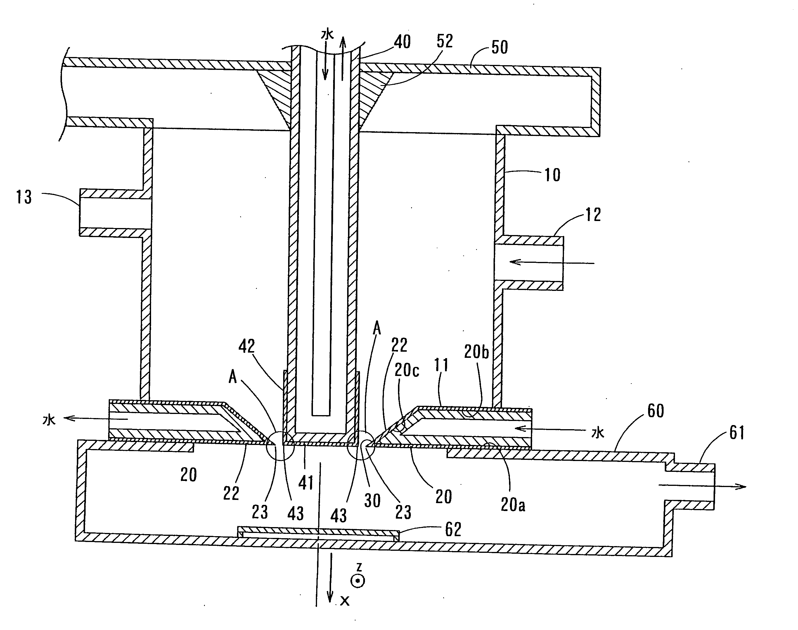
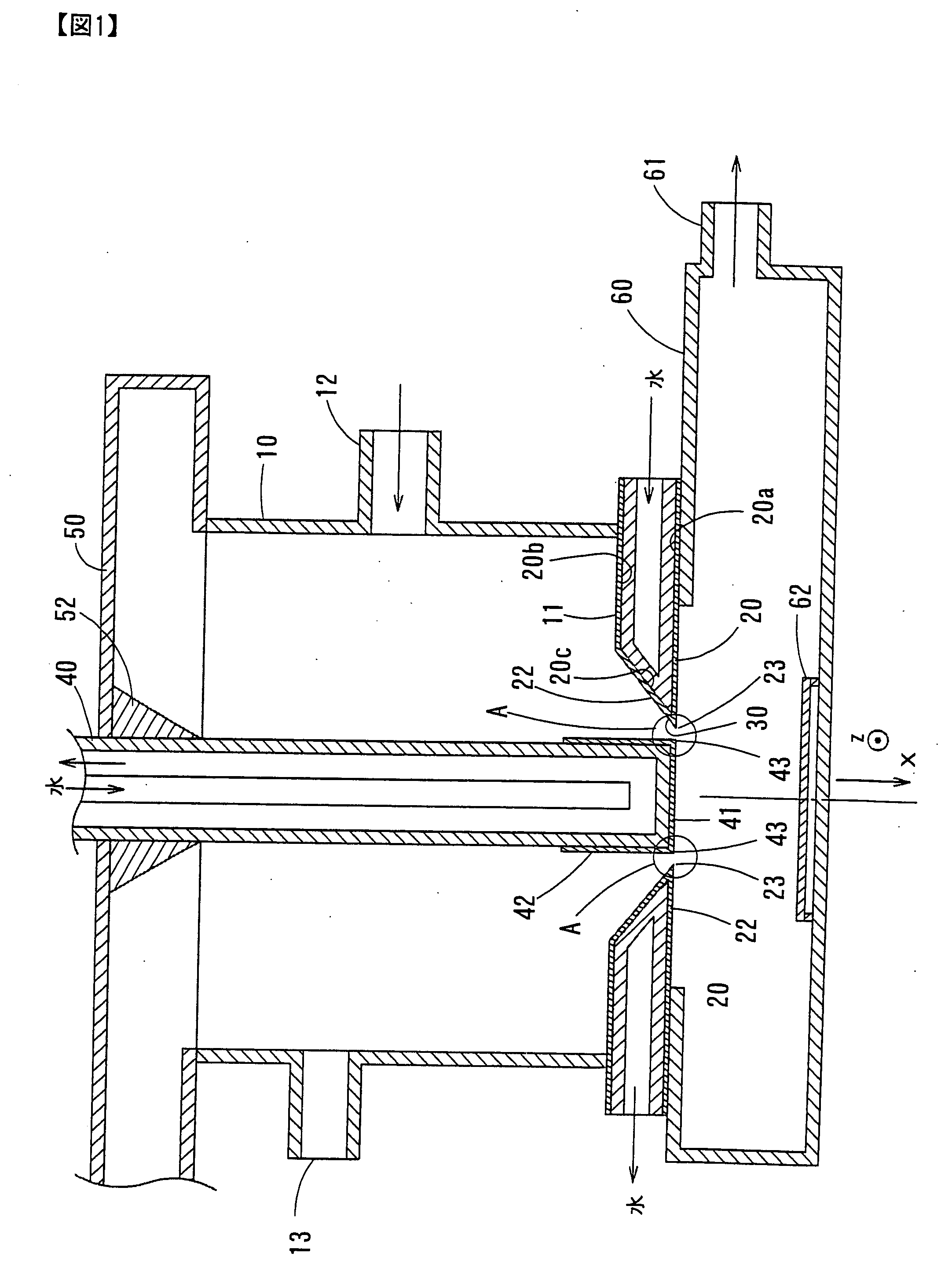
[0046]FIG. 1 shows an example of a plasma generation apparatus used for decomposition and synthesis of a CF4 gas. A tubular casing 10 is formed of copper, and for a bottom surface 11 thereof, an electrode 20 composed of a disc-shaped conductor is provided. A circular hole 30 having a radius of 8 mm is provided in the central portion of the disc-shaped electrode 20. The side-surface cross-section of the electrode 20 is formed to have a taper so that the diameter of the hole 30 is decreased in the outside direction (in the x-axis direction).

[0047]An outer surface 20a, an inner surface 20b and a side surface 20c of this electrode 20 are covered with an insulating film 22 composed of Al2O3 having a thickness of 150 μm. In addition, the electrode 20 is formed so that cooling water is supplied therein for circulation and reaches the portion forming the hole 30 at the front end, that is, is formed so as to cool the hole 30 of the electrode 20.

[0048]A central conductor 40 is provided along ...

example 2

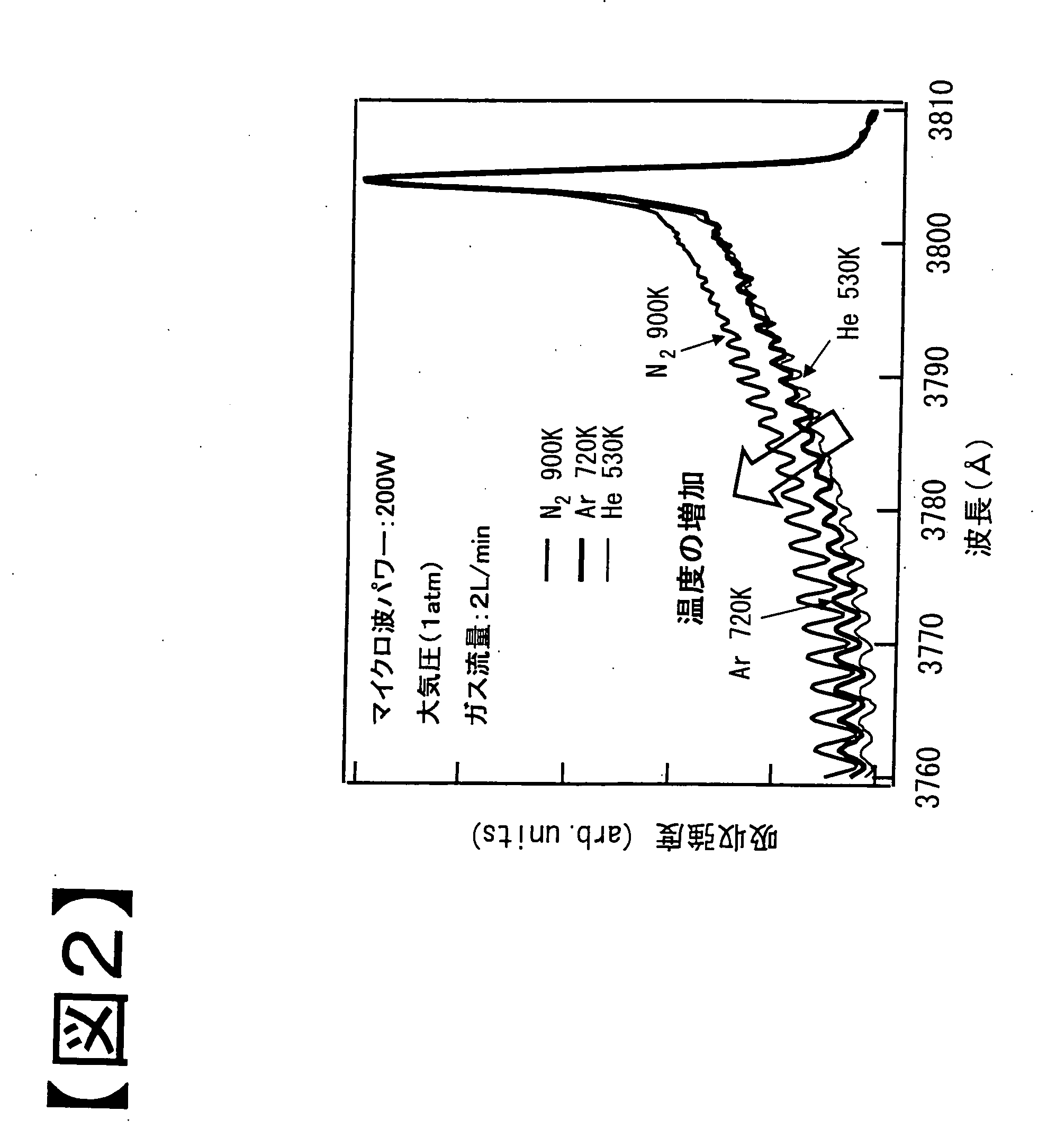
[0053]Next, by using the above apparatus, an Ar gas and a N2 gas were used instead of a He gas. Since a He gas is expensive, when an Ar gas and a N2 gas can be used, significant industrial advantages can be obtained. Hence, first of all, by using an apparatus in which the insulating film 22 and the insulating film 42 are not formed on the metal electrode 20 and the central conductor 40, respectively, experiments were each carried out by continuous supply of a microwave having an electric power of 200 W. However, the electrode 20 and the central conductor 40 were cooled by circulating cooling water, and the pressure was set to atmospheric pressure. Three experiments, that is, an experiment in which a He gas was supplied at a flow rate of 2 L / min, an experiment in which an Ar gas was supplied at a flow rate of 2 L / min, and an experiment in which a N2 gas was supplied at a flow rate of 2 L / min, were carried out. As a result, in the case of a He gas, the generation of stable plasma was ...

example 3

[0056]Next, the plasma temperature with time from the application of microwave was measured in a manner similar to that in Example 2. The results are shown in FIG. 3. A microwave having a frequency of 2.45 GHz and an electric power of 300 W was introduced into the casing 10 under the condition similar to that in Example 2. Subsequently, He, Ar, and N2 gases were separately introduced, and the change in plasma temperature was separately measured. From the results shown in FIG. 3, it is understood that although the temperature increase is not observed in the cases of He and Ar, the temperature is rapidly increased in the case of N2. From the above measurement results, the inventors of the present invention assumed that in order not to increase the plasma temperature, when a pulse wave is used as the microwave, and the cycle period and the pulse width are controlled so as to control the duty ratio, the plasma is cooled while the microwave is not applied. Accordingly, the inventors of t...


PUM

PropertyMeasurementUnit
pressureaaaaaaaaaa
angleaaaaaaaaaa
angleaaaaaaaaaa

Abstract

[Object] To stably generate plasma at atmospheric pressure.[Solving Means] There are provided a tubular casing 10 into which a gas and a microwave are introduced, a hole 30 provided in a bottom surface of this casing, and a columnar conductor 40 which is provided in an axis direction of the casing, a bottom surface of the conductor 40 having a contour placed inside the contour of the hole. A minute gap A formed between the contour of a bottom surface 41 of the conductor 40 and the contour of the hole, a coaxial waveguide formed of the conductor and the casing, and an insulating film 22 formed at least on a contour portion forming the hole at the minute gap are provided. In the structure described above, the microwave is guided to the minute gap by the coaxial waveguide, and the gas is made to pass through the minute gap, so that the gas is placed in a plasma state at the minute gap. The microwave is a pulse wave and is duty-controlled, and the contour portion forming the hole 30 is cooled with a cooling medium from the inside of an electrode 20. Accordingly, the increase in plasma temperature can be prevented, and as a result, stable plasma can be generated.

Description

TECHNICAL FIELD [0001]The present invention relates to an apparatus which stably obtains plasma. The present invention particularly relates to an apparatus which stably obtains plasma using a microwave at atmospheric pressure (without being evacuated by a factor other than a gas flow). For example, the above apparatus may be used as an apparatus which decomposes a fluorocarbon gas used in a semiconductor etching process, a film-forming process, or the like and which recovers the above gas in the form of particles.BACKGROUND ART [0002]In recent years, in an etching step and a film-forming step of a semiconductor process, plasma of a fluorocarbon gas has been used. For example, in order to increase the degree of integration of a semiconductor integrated circuit, an ultrafine fabrication technique and an epitaxial growth technique must be improved, and in particular, the improvement in ultrafine fabrication technique is absolutely necessary. In this ultrafine fabrication technique, imp...

Claims


Application Information

Patent Timeline
Patent Type & Authority Applications(United States)
IPC IPC(8): H01L21/205H01L21/304H01L21/3065H05H1/24
CPCH05H1/24H05H1/46H05H1/463H05H1/4622
Inventor GOTO, TOSHIOHORI, MASARUDEN, SHOJINAGAI, MIKIO
Owner GOTO TOSHIO
Why Eureka
Try Eureka