Laser scribing apparatus, systems, and methods

a laser scribing and writing device technology, applied in the direction of manufacturing tools, sustainable manufacturing/processing, final product manufacturing, etc., can solve the problems of electrical shorts, difficult to create narrow grooves between photovoltaic cells, and problems known to occur within the haz

Inactive Publication Date: 2008-02-07
SOLYNDRA
View PDF65 Cites 235 Cited by
  • Summary
  • Abstract
  • Description
  • Claims
  • Application Information

AI Technical Summary

Problems solved by technology

However, even when a TCO layer is present, a bus bar network 120 is typically needed in conventional solar cells to draw off current since the TCO has too much resistance to efficiently perform this function in larger solar cells.
This is because hard or brittle materials often break or shatter during mechanical scribing, making it difficult to create narrow grooves between photovol

Method used


Image

  • Laser scribing apparatus, systems, and methods
  • Laser scribing apparatus, systems, and methods
  • Laser scribing apparatus, systems, and methods

Examples


Embodiment Construction

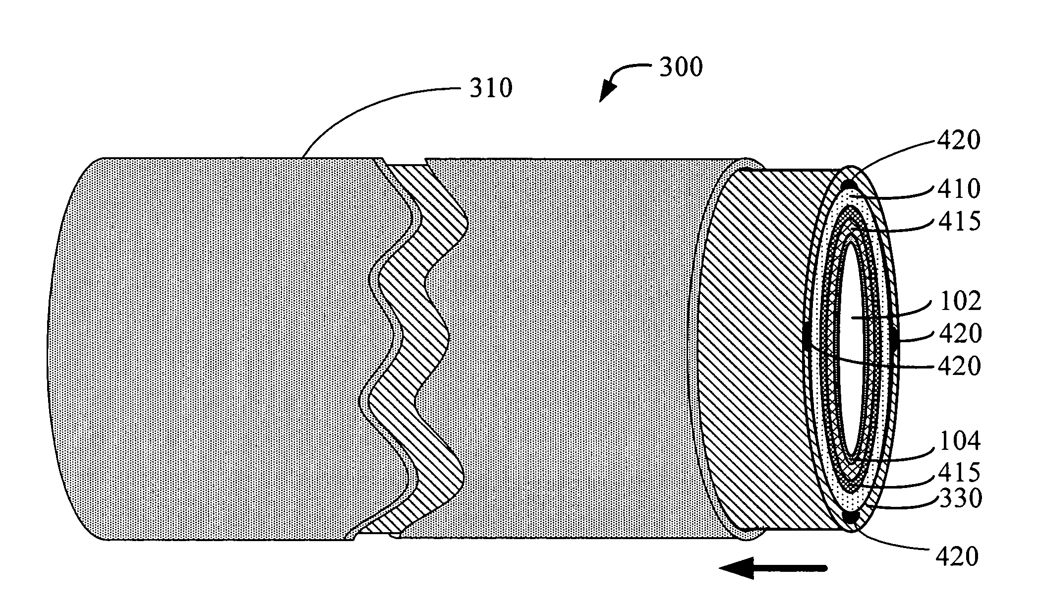
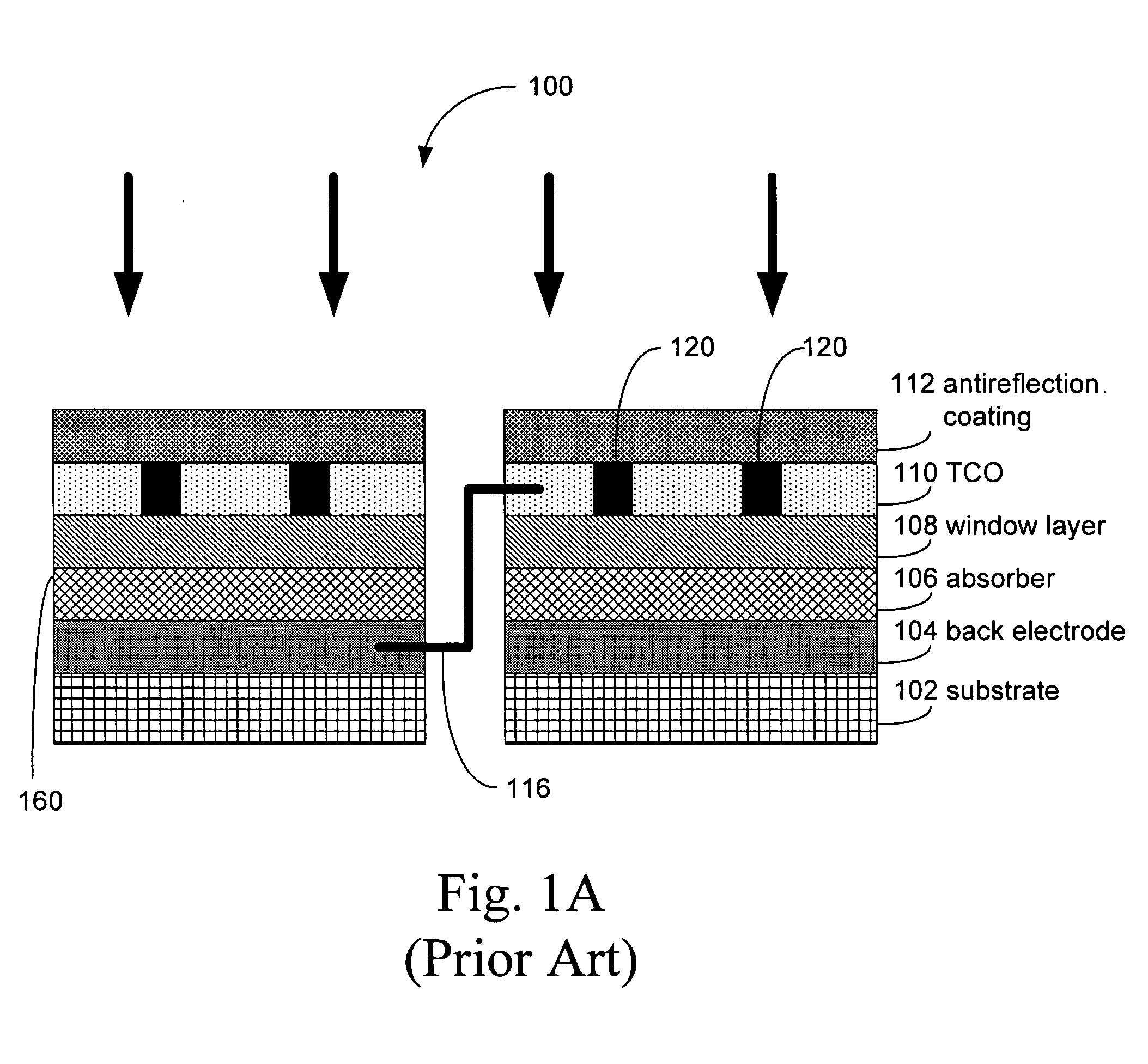
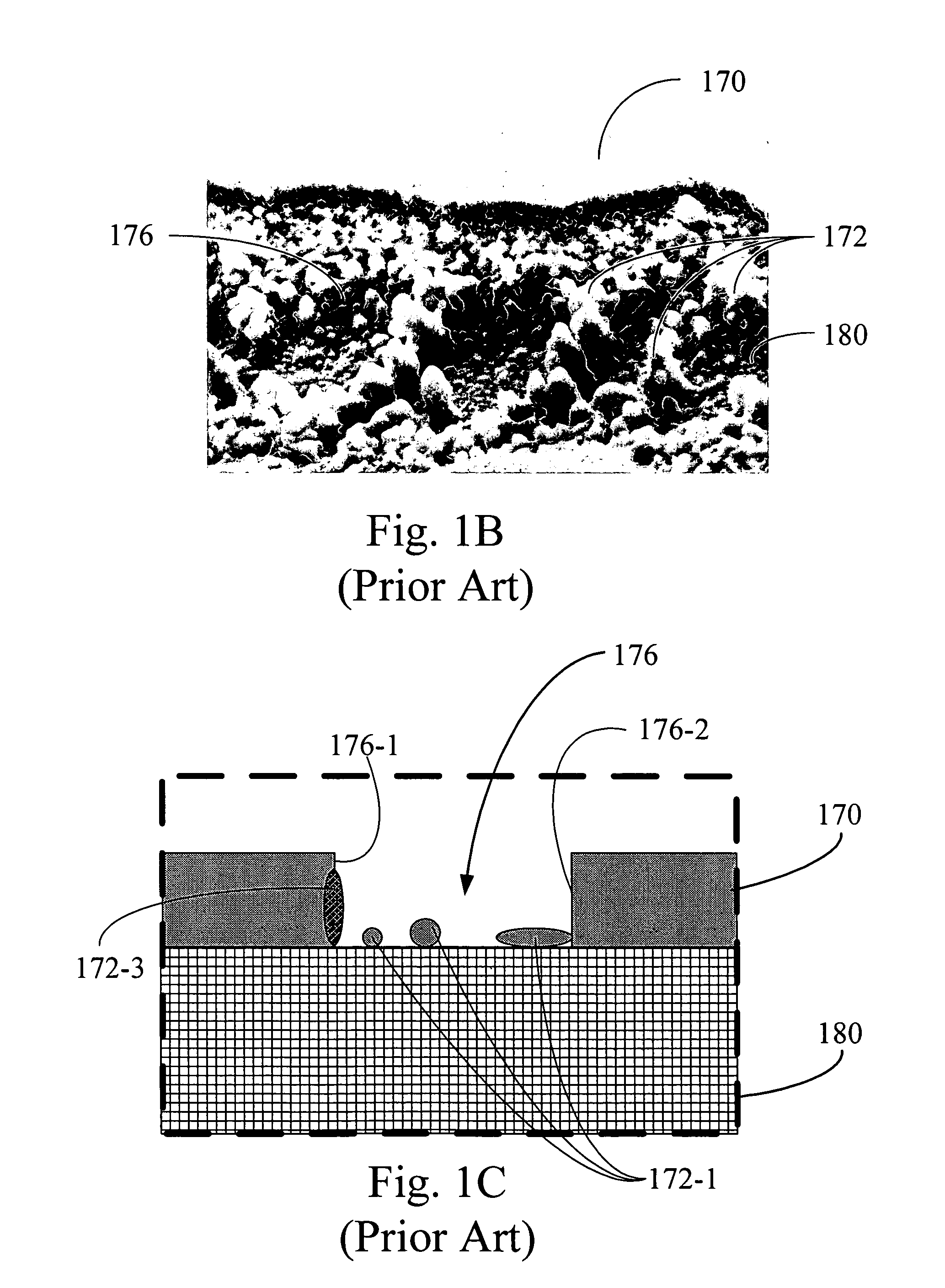
[0030]Disclosed herein are apparatus, systems, and methods for laser scribing. Such apparatus, systems, and methods can be used for a wide range of applications such as for manufacturing solar cells that convert solar energy. When such apparatus, systems, and methods are used to construct solar cells, they have the advantage of reducing or eliminating the presence shunts in such solar cells. Solar cells constructed by the disclosed apparatus, systems, and methods may have elongated cylindrical or planar shapes. More generally, the present invention can be used to facilitate a broad array of micromachining techniques including microchip fabrication. Micromachining (also termed microfabrication, micromanufacturing, micro electromechanical systems) refers to the fabrication of devices with at least some of their dimensions in the micrometer range. See, for example, Madou, 2002, Fundamentals of Microfabrication, Second Edition, CRC Press LLC, Boca Raton, Fla., which is hereby incorporat...


PUM

PropertyMeasurementUnit
Frequencyaaaaaaaaaa
Frequencyaaaaaaaaaa
Surface energyaaaaaaaaaa

Abstract

Apparatus, systems, and methods for forming a photovoltaic cell from a common layer on a substrate are provided. A first pass is made with a first laser beam over an area on the common layer. The first pass forms a groove in the common layer. The first pass forms within the common layer a first edge and a second edge. The first edge is separated from the second edge by the groove. The groove provides a first level of electrical isolation between the first edge and the second edge. A second pass is made with a second laser beam over approximately the same area on the common layer. The second pass provides a second level of electrical isolation between the first edge and the second edge. The second level of electrical isolation is greater than the first level of electrical isolation.

Description

1. FIELD OF THE APPLICATION[0001]This application relates to using laser scribing techniques.2. BACKGROUND OF THE APPLICATION[0002]Solar cells are typically fabricated as separate physical entities with light gathering surface areas on the order of 4-6 cm2 or larger. For this reason, it is standard practice for power generating applications to mount the cells in a flat array on a supporting substrate or panel so that their light gathering surfaces provide an approximation of a single large light gathering surface. Also, since each cell itself generates only a small amount of power, the required voltage and / or current is realized by interconnecting the cells of the array in a series and / or parallel matrix.[0003]A conventional prior art solar cell structure is shown in FIG. 1. Because of the large range in the thickness of the different layers, they are depicted schematically. Moreover, FIG. 1 is highly schematic so that it represents the features of both thick-film solar cells and th...

Claims


Application Information

Patent Timeline
IPC IPC(8): H01L31/00
CPCB23K26/0608H01L31/046B23K26/0635B23K26/0656B23K26/073B23K26/0736B23K26/0823B23K26/367B23K26/4075B23K26/409B23K2201/40H01L31/022425H01L31/206Y02E10/50B23K26/0621B23K26/40B23K26/0619B23K26/0624B23K26/066B23K26/364B23K2101/40B23K2103/172B23K2103/50H01L31/0463H01L31/0465Y02P70/50
Inventor MILSHTEIN, ERELBULLER, BENYAMIN
Owner SOLYNDRA
Why Eureka
Try Eureka