Supporting column having porous structure

a support column and porous structure technology, applied in the field of supporting columns, can solve the problems of aging, overloading a power supply, and generating noise, and achieve the effect of less susceptible to structural damage and favorable to heat dissipation

Inactive Publication Date: 2008-02-07
INVENTEC CORP
View PDF20 Cites 19 Cited by
  • Summary
  • Abstract
  • Description
  • Claims
  • Application Information

AI Technical Summary

Benefits of technology

[0018]Compared to the prior art, the present invention discloses a supporting column having both a supporting body and a porous structure, wherein the supporting body not only supports the porous structure and thereby protects the porous structure from damage done by an external force, but also supports the chamber and thereby prevents the chamber from being deformed by an external force.
[0019]In short, the present invention discloses a supporting column having both a supporting body and a porous structure, wherein porous structure is structurally reinforced and thereby is less susceptible to structural damage but is more conducive to heat dissipation by a cooler.

Problems solved by technology

In recent years, CPU operating voltage increases with the ever-increasing CPU performance, which causes a typical CPU to generate an ever-increasing amount of unwanted heat.
But indiscriminately increasing the cooling fan rotation speed for the sake of efficient heat dissipation inevitably overloads a power supply and produces noise.
Although heat pipe technology enhances the efficiency of heat dissipation performed by the cooler 1, it has its own drawbacks.
After functioning, that is, drawing in and delivering the working fluid, for a long period of time, the columns 15 is susceptible to aging—peeling off and resultant structural damage.
Formed by powder sintering, the columns 15 are likely to be fragile.

Method used


Image

  • Supporting column having porous structure
  • Supporting column having porous structure
  • Supporting column having porous structure

Examples


first embodiment

The First Embodiment

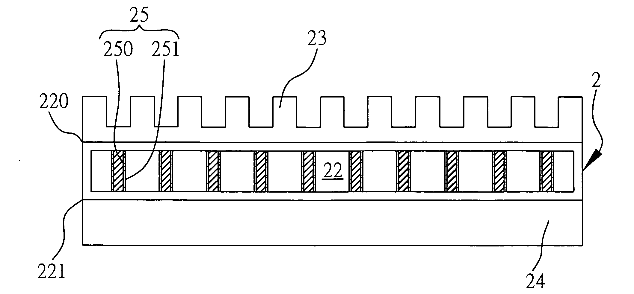
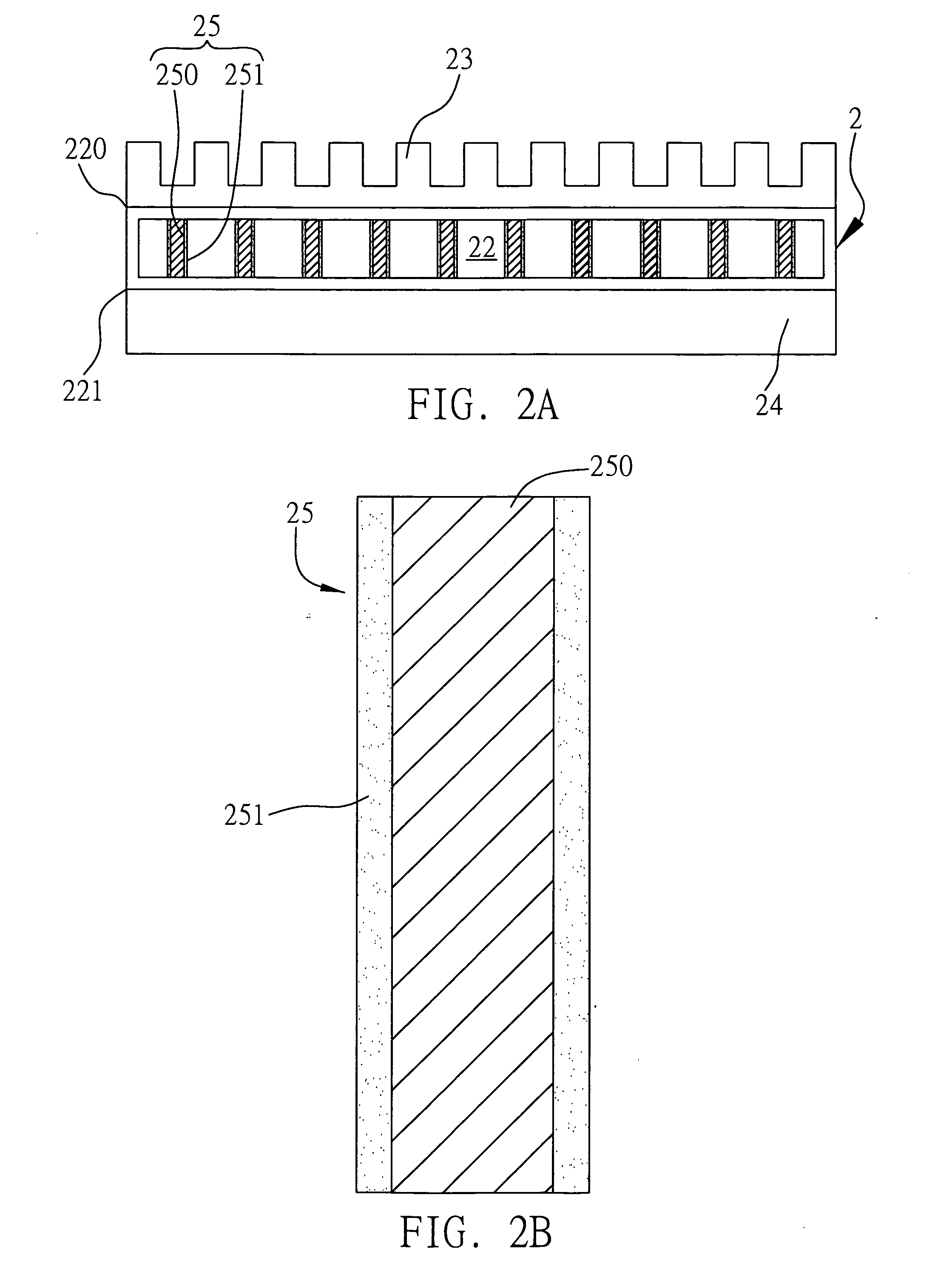
[0029]Referring to FIG. 2A, a cooler 2 comprises a chamber 22 including a condensation side 220 and an evaporation side 221. Disposed on the condensation side 220 is a cooling fin 23. In contact with the evaporation side 221 is a heat generating element 24 like a CPU. The chamber 22 is filled with working fluid of a low boiling point. The heat generating element 24 in operation generates heat, and thus the working fluid is heated up and evaporated into gas. Heat dissipation is carried out by means of the cooling fin 23 such that the gas is condensed into liquid. Accordingly, heat dissipation is achieved by phase cycling of the working fluid.

[0030]The present invention discloses a supporting column 25 having both a supporting body 250 and a porous structure 251. The supporting column 25 is disposed inside the chamber 22. Two ends of the supporting column 25 are connected to the evaporation side 221 and the condensation side 220. The porous structure 251 is formed ...

second embodiment

The Second Embodiment

[0031]FIG. 3 is a top plan view of the second embodiment of a supporting column of the present invention. This embodiment differs from the first embodiment in two ways. In this embodiment, a plurality of grooves 250a are formed on the supporting body 250, and cross sections of the grooves 250a are triangular in shape or in any processing friendly shape, for example, rectangular.

third embodiment

The Third Embodiment

[0032]FIG. 4 is an elevational view of the third embodiment of a supporting column of the present invention. This embodiment differs from the preceding embodiment in the way that the porous structure 251 comprises metal wire netting 252 so as to provide capillarity by tiny meshes.


PUM


Abstract

A supporting column having a porous structure is installed in a chamber filled with working fluid. The chamber includes an evaporation side for evaporating the working fluid to the gaseous phase, and a condensation side opposite the evaporation side for condensing the gaseous phase to the liquid phase. The supporting column includes a supporting body and the porous structure formed on the supporting body. Two ends of the supporting body are connected to the evaporation side and the condensation side respectively. The porous structure is supported by the supporting body and configured to convey the working fluid. Accordingly, heat dissipation is achieved by phase cycling of the working fluid.

Description

BACKGROUND OF THE INVENTION[0001]1. Field of the Invention[0002]The present invention relates to a supporting column, and more particularly, to a supporting column having a porous structure and installed in a chamber filled with working fluid, thus conveying the working fluid with a view to achieving heat dissipation.[0003]2. Description of Related Art[0004]In 1963, G. M. Grover invented heat pipe technology. A heat pipe is a heat transmitting device based on the principles of heat transfer as well as a property of cooling media—rapid heat transfer. A heat pipe is typically fully-sealed and vacuum-maintained so as to facilitate rapid heat transfer through evaporation and condensation. It has other advantages, namely adjustable heat transfer areas on both the cold and hot interfaces, long-distance heat transfer, and controllable temperature. A heat exchanger composed of heat pipes has advantages, such as efficient heat transfer, compact structure, and low flow impedance. Accordingly,...

Claims


Application Information

Patent Timeline
Patent Type & Authority Applications(United States)
IPC IPC(8): F28D15/00
CPCF28D15/046
Inventor HSIAO, WEI-CHE
Owner INVENTEC CORP
Why Eureka
Try Eureka