Multi zone cracking furnace

a multi-zone cracking and furnace technology, applied in the field of multi-zone cracking furnaces, can solve the problems of insufficient prior art efforts to meet the increased capacity and flexibility requirements of a single furnace, and none of the currently available furnace technologies are suitable, and achieve the effect of increasing the flexibility of pyrolysis cracking

Inactive Publication Date: 2008-02-07
STONE & WEBSTER PROCESS TECH
View PDF3 Cites 17 Cited by
  • Summary
  • Abstract
  • Description
  • Claims
  • Application Information

AI Technical Summary

Benefits of technology

[0007] It is an object of the present invention to provide an improved apparatus and pro

Problems solved by technology

Because each different feedstock and desired product slate entails the use of different reaction conditions, primarily, reaction temperature and reaction residence time, none of the current

Method used


Image

  • Multi zone cracking furnace
  • Multi zone cracking furnace
  • Multi zone cracking furnace

Examples


Embodiment Construction

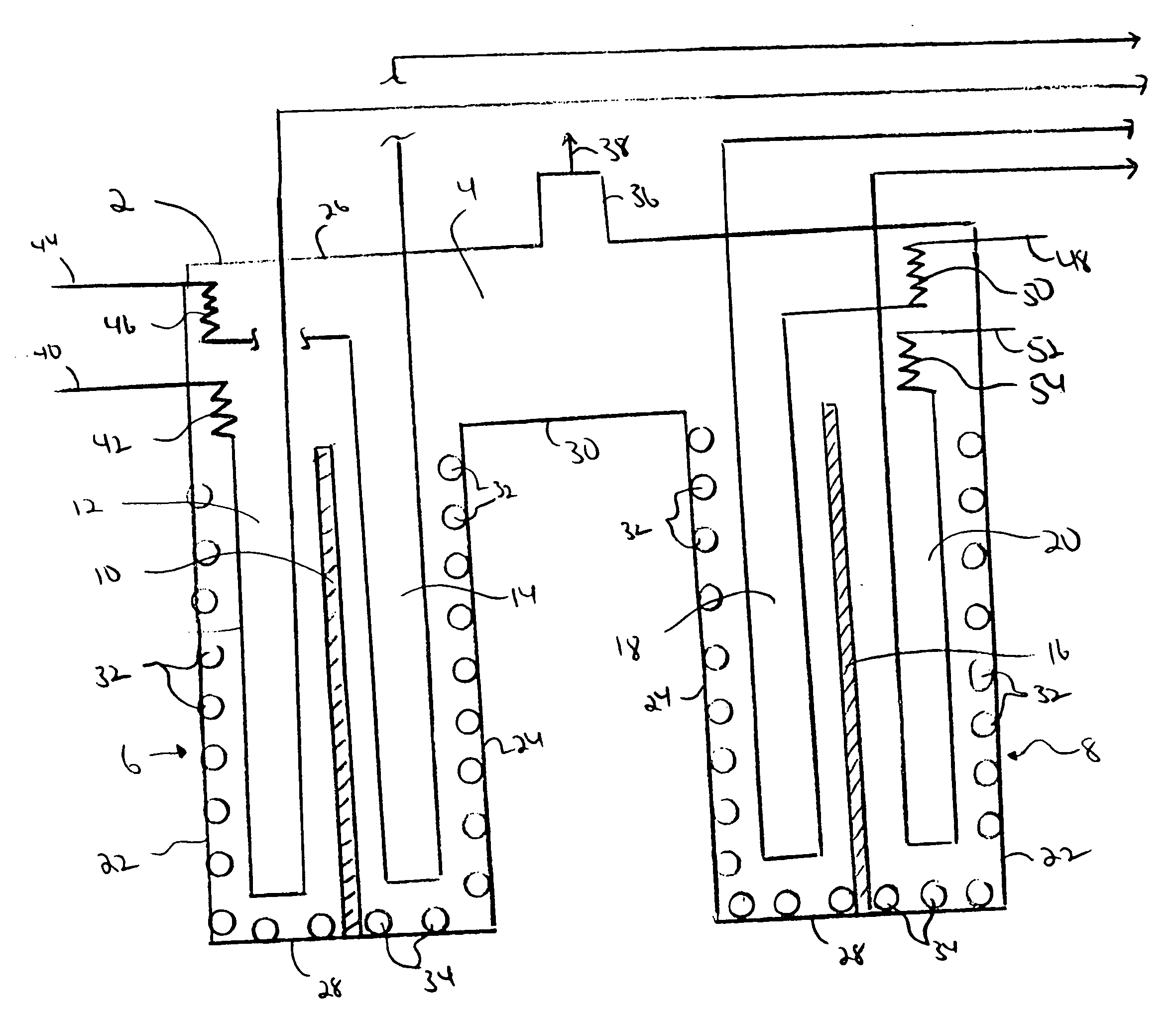
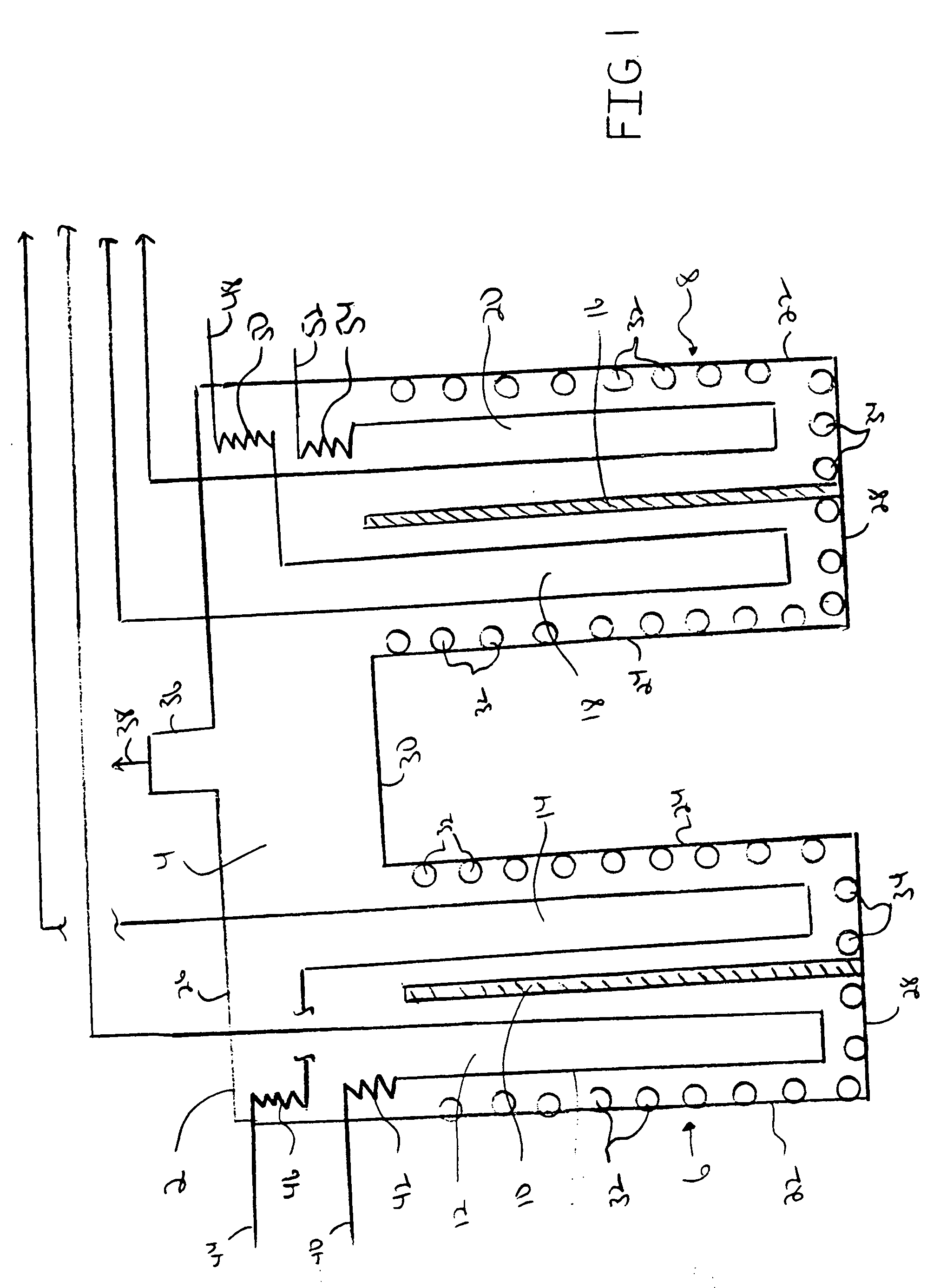
[0011] The multi zone cracking furnace of the present invention will be described in relation to the furnace of FIG. 1 which has four separate and independent cracking zones. However, it is to be understood that the present application is not limited in any way to this detailed description, and all obvious modifications which this detailed description suggests to those of ordinary skill in the art are also contemplated by the present application and the appended claims.

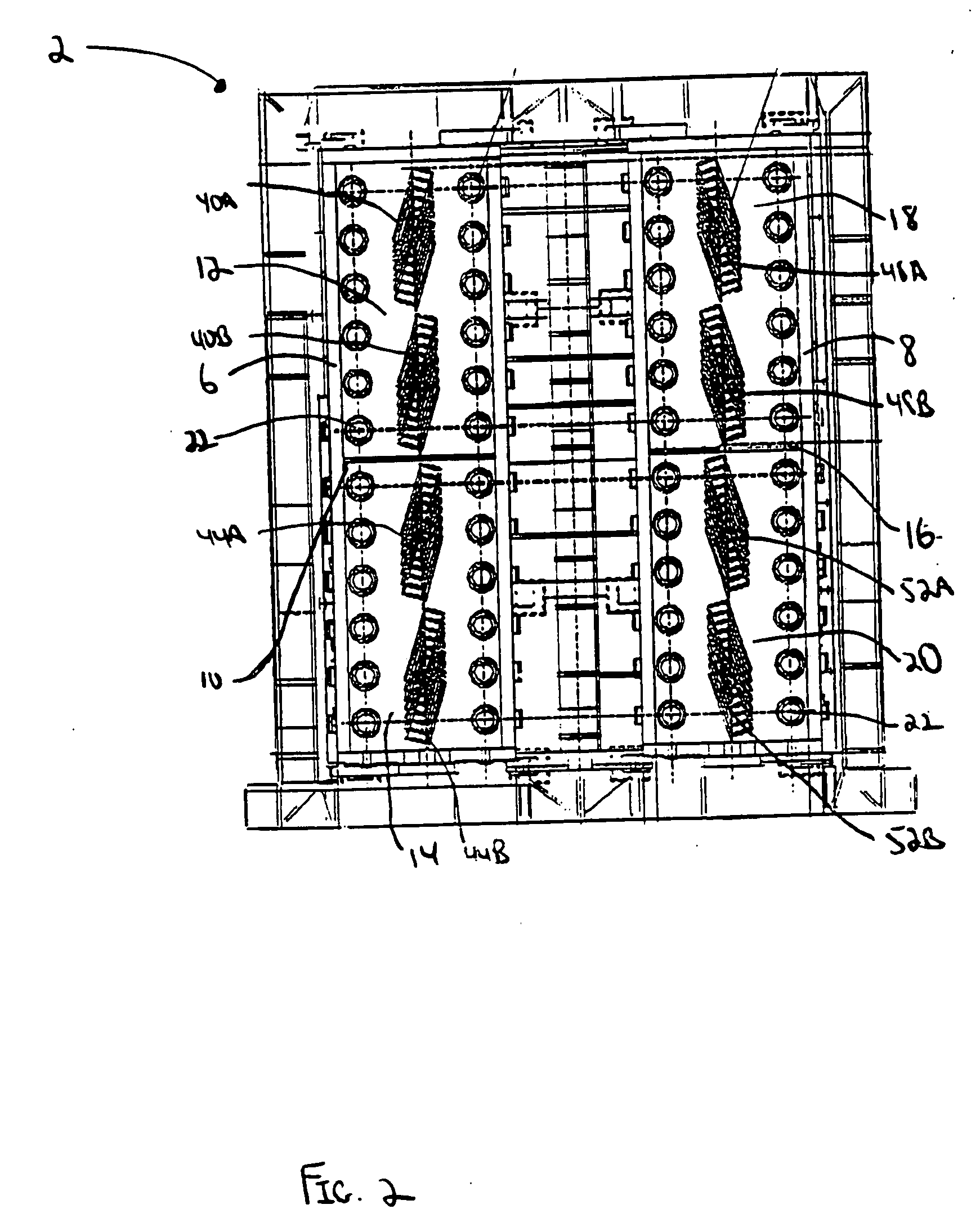
[0012] Referring to FIGS. 1 and 2, there is a shown a multizone pyrolysis furnace 2 of the present invention. The furnace 2 is provided with a convection section 4, a first fired radiant chamber 6 and a second fired radiant chamber 8. The first fired radiant chamber 6 is provided with a dividing wall 10 to divide the first radiant chamber 6 into a first separate independent radiant zone 12 and a second separate independent radiant zone 14. The second fired radiant chamber 8 is provided with a dividing wall 16 to divi...


PUM


Abstract

An improved furnace which provides for multizone, separate and independent cracking is provided.

Description

FIELD OF THE INVENTION [0001] The present invention relates generally to an apparatus for thermally cracking a hydrocarbon feedstock. More particularly the present invention relates to an apparatus for providing improved operational flexibility of the furnace. BACKGROUND OF THE PRESENT INVENTION [0002] The petrochemical industry has long used hydrocarbon feedstocks for the production of valuable olefinic materials, such as ethylene and propylene. Ideally, commercial operations have been carried out using normally gaseous hydrocarbons such as ethane and propane as the feedstock. As the lighter hydrocarbons have been consumed and the availability of the lighter hydrocarbons has decreased, the industry has more recently been required to crack heavier hydrocarbons, such as naphthas and gas oils. [0003] A typical process for the production of olefins from hydrocarbon feedstocks is the thermal cracking process. In this process, hydrocarbons undergo cracking at elevated temperatures to pro...

Claims


Application Information

Patent Timeline
IPC IPC(8): C10G9/14B01J6/00C10G9/20
CPCB01J6/008B01J2219/00083Y10S585/921B01J2219/00157C10G9/20B01J2219/00155
Inventor BREWER, JOHNBROWN, DAVIDRUMBOLD, SVEND
Owner STONE & WEBSTER PROCESS TECH
Why Eureka
Try Eureka