Semiconductor light source packages with broadband and angular uniformity support

a technology of electromagnetic radiation and light source, applied in the field of electromagnetic radiation light source, can solve the problems of difficult work and manipulation of resin based binding materials, design relates to angular uniformity, and the production of mechanical dispersants suitable for resin use is rather complex, so as to achieve high angular uniformity and improve the effect of optical output bandwidth and uniformity

Inactive Publication Date: 2008-02-07
LIGHT ENGINES CORP
View PDF27 Cites 16 Cited by
  • Summary
  • Abstract
  • Description
  • Claims
  • Application Information

AI Technical Summary

Benefits of technology

[0010]Comes now, Aliyev, Y. T. and Shishov, A. V. with inventions of optical sources including packages arranged to provide bandwidth and uniformity improvements in optical outputs. It is a primary function of these optical systems to provide optical beams having high angular uniformity and broadband or ‘white’ light output. Particularly, these packages are arranged in special, easy-to-manufacture arrangements which permit inexpensive construction which cooperates with manual and automated fabrication processing.

Problems solved by technology

No matter the precise nature of these designs, it is always a material issue to consider optical matching between these components for best control of output characteristics.
One difficulty which accompanies many LED package designs relates to angular uniformity.
At high concentrations of mechanical dispersant, these resin based binding materials becomes difficult to work and manipulate.
In addition, producing mechanical dispersants suitable for use with resin is rather complex technological process demanding formation of particles with appropriate and regular size, shape and refractive index.
The art is troubled by ineffective dispersant systems and alternatives are widely sought.
While systems and inventions of the art are designed to achieve particular goals and objectives, some of those being no less than remarkable, these inventions have limitations which prevent their use in new ways now possible.

Method used


Image

  • Semiconductor light source packages with broadband and angular uniformity support
  • Semiconductor light source packages with broadband and angular uniformity support
  • Semiconductor light source packages with broadband and angular uniformity support

Examples


Embodiment Construction

[0031]In accordance with each of preferred embodiments of these inventions, there is provided semiconductor optical sources having output with a high degree of angular uniformity. It will be appreciated that each of embodiments described include apparatus and the apparatus of one preferred embodiment may be different than the apparatus of another embodiment.

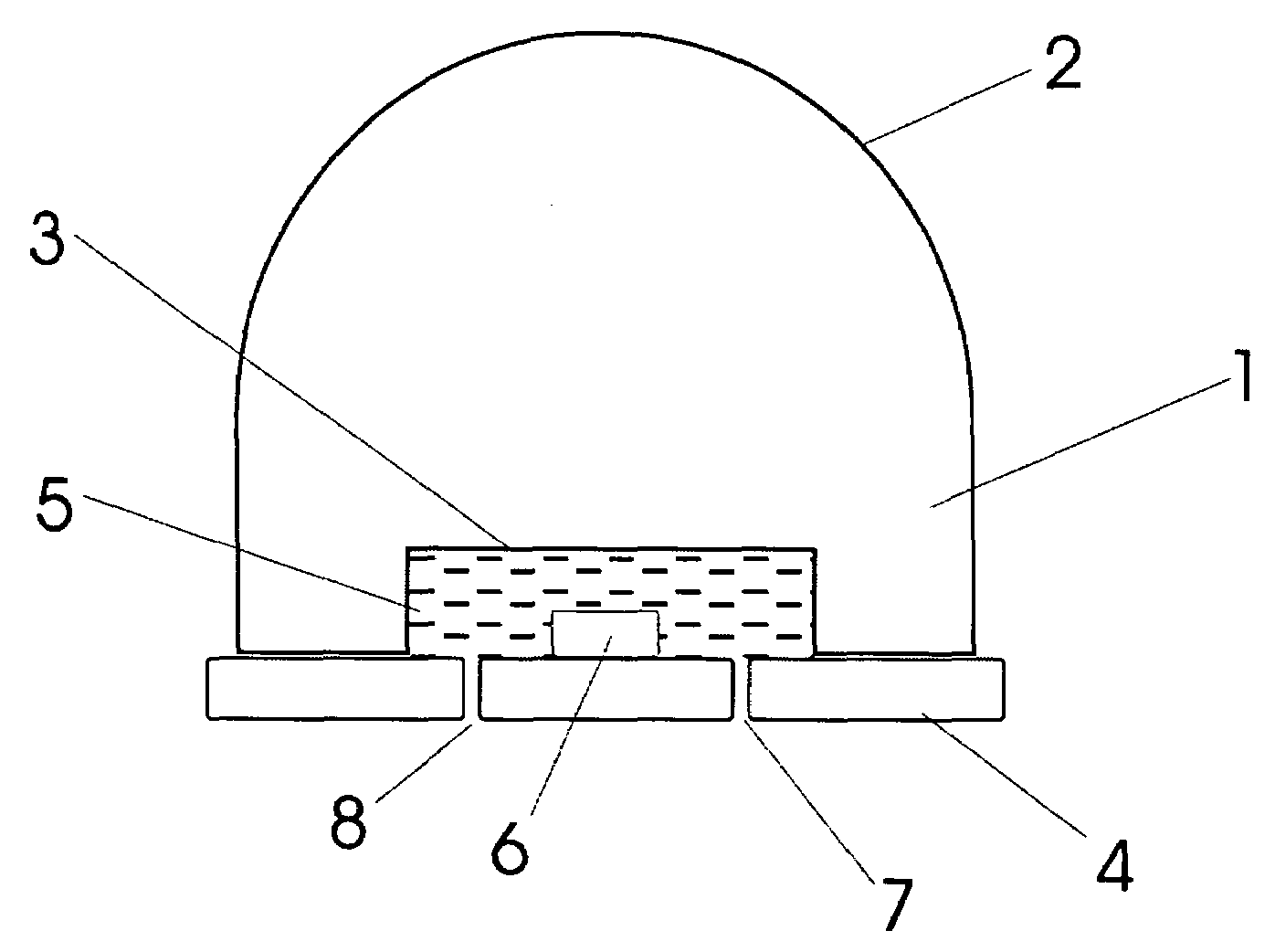
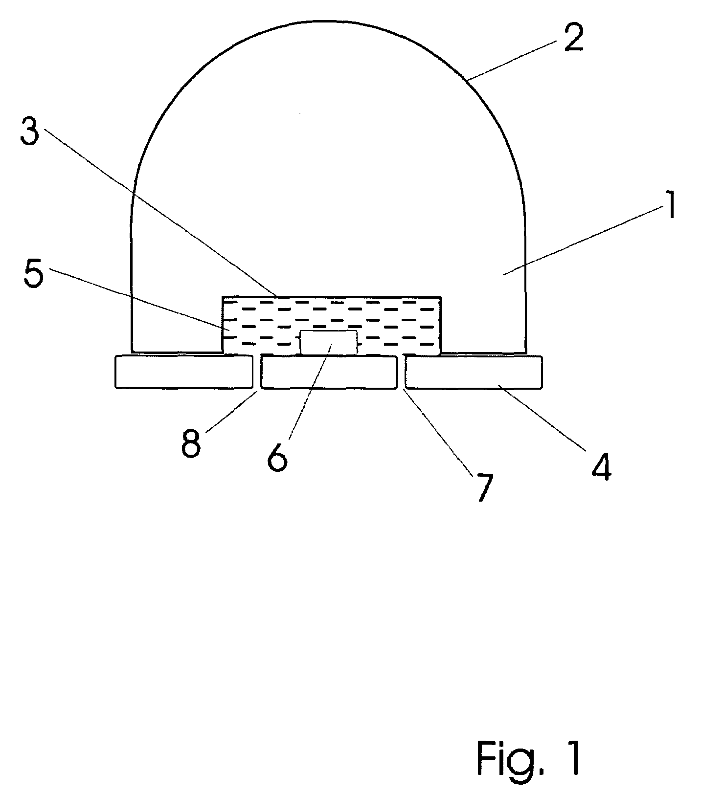
[0032]Typical semiconductor light sources are generally referred to as ‘LED’s or light emitting diodes. While special cases include semiconductor lasers, in general we consider diode source whether or not stimulated emission is included. When considering these sources, one may refer to them as an ‘LED’. However the name seems to only include the diode but not the supporting package in contrast to its common use. By ‘LED’, it is meant in the arts that the semiconductor chip, its electrical supports and mechanical supports are included. Thus, LED includes the diode semiconductor and the supporting package and systems.

[0033]Special ...


PUM


Abstract

Optical sources presented are comprised of a semiconductor emitter and supporting package system including a hard plastic lens cover and mounting substrate with electrical and mechanical support for the semiconductor. A cavity is formed between the lens cover and substrate which supports addition of materials which cooperate with optical propagation and produce some interaction or effect with respect to the beam. Some versions include dispersants and wavelength shifting materials. In any case, the arrangement and spatial distribution of these materials is not trivial. Both the cavity shape and material placement effect the final output of systems produced here. Well designed filling ports in the substrate permit injection of viscous material such that some preferred spatial distribution is realized. Filling port position may cooperate with separate cavities or may merely encourage natural distribution dictated by flow properties of the materials.

Description

BACKGROUND OF THESE INVENTIONS[0001]1. Field[0002]The following inventions disclosure is generally concerned with semiconductor light sources and specifically concerned with light source package construction and arrangement to effect preferred optical outputs regarding spectral and beam uniformity characteristics.[0003]2. Prior Art[0004]Some light emitting diode LED designs include systems having a semiconductor die immersed in a resin which forms a lens with an air interface. In other designs, light from the die first enters a cavity of air, then enters a transparent plastic (resin / polymer) body formed as a lens having a spherical surface. In advanced designs, the cavity described above may be filled with certain compounds which permit light transmission and sometimes additionally impart some action / effect on light passing therethrough. No matter the precise nature of these designs, it is always a material issue to consider optical matching between these components for best control...

Claims


Application Information

Patent Timeline
Patent Type & Authority Applications(United States)
IPC IPC(8): H01L33/00H01L33/50H01L33/52H01L33/58
CPCH01L33/501H01L33/58H01L33/54H01L33/52
Inventor SHISHOV, ALEXANDER VALERIEVICHALIYEV, YEVGUENI TOFIK
Owner LIGHT ENGINES CORP
Why Eureka
Try Eureka