Collimator array

a collimator array and fiber technology, applied in the field of fiber optical collimator arrays, can solve the problems of cost advantage loss and other methods of molding, and achieve the effect of reducing the relative alignment accuracy of each channel and reducing the cost advantag

Active Publication Date: 2008-02-07
II VI DELAWARE INC
View PDF6 Cites 11 Cited by
  • Summary
  • Abstract
  • Description
  • Claims
  • Application Information

AI Technical Summary

Benefits of technology

[0009] A particular advantage of the present invention over prior art collimator arrays becomes apparent if the element is made by molding, since both the lens and the fiber hole arrays are formed in a single element with the same mold, such that the accuracy of alignment is determined by the accuracy of the mold, which can be significantly higher than the mechanical aligning procedures used in prior art assembled arrays. Furthermore, due to the small distances between each fiber hole and its associated lens, the relative alignment accuracy of each channel is much better than the total accuracy of the part, which may have an accumulated accuracy drift across its width. However, it is to be understood that the monolithic block structure of the collimator array of the present invention may also have advantages over prior art assembled collimator arrays, even if the collimator block is manufactured by some other process, such as precision single-point machining, or for micro-arrays, by microelectronic machining methods, and this application is to be understood to cover collimator arrays blocks as manufactured by any such methods, and not just by molding. However, the cost advantage may be lost using methods other than molding.
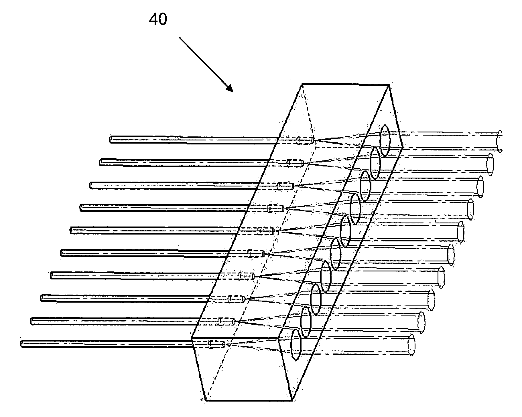
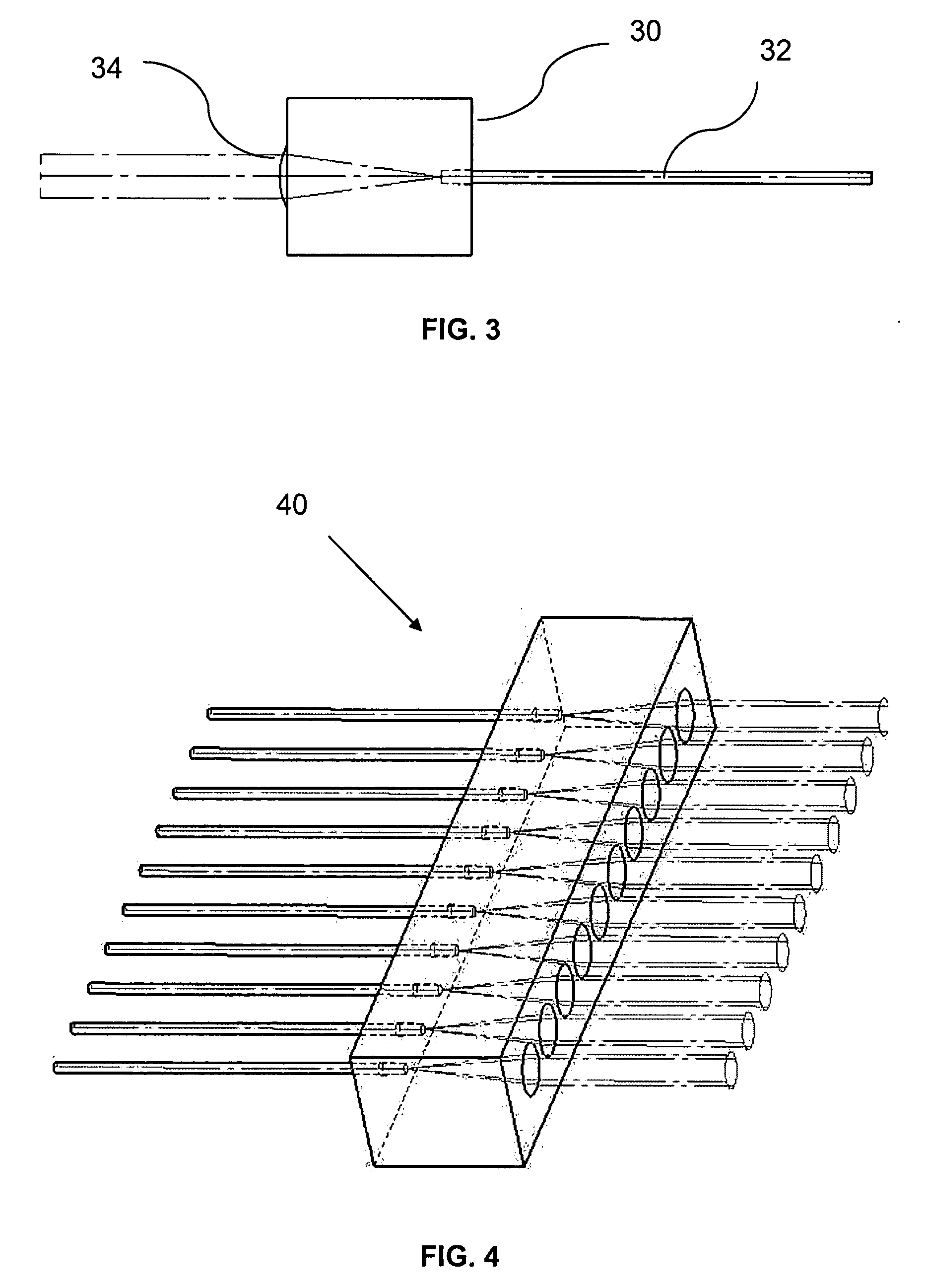
[0010] There is thus provided in accordance with a preferred embodiment of the present invention, a collimator array comprising:
[0011] wherein the array of holes and the array of lenses are generally located such that the lateral spacing between adjacent ones of the lenses is the same as the lateral spacing between adjacent ones of the holes, and successive ones of the array of lenses are generally aligned to receive light emitted from fibers inserted into successive ones of the array of holes.
[0012] In the above described collimator array, the array of holes may preferably be formed in a first surface of the block, and the array of lenses formed in a second surface of the block, the first surface being disposed opposite the second surface, such that light from ends of the optical fibers is transmitted directly to the lenses. Alternatively and preferably, the array of holes may be formed in a first surface of the block, and the array of lenses formed in a second surface of the block, the first surface being disposed at an angle to the second surface, and wherein the block also comprises a third reflective surface disposed such that light from ends of the optical fibers is transmitted by reflection in the third surface to the lenses.
[0013] There is further provided in accordance with yet another preferred embodiment of the present invention, a collimator array as described above, and wherein the array of holes and the array of lenses are formed in a first surface of the block, and wherein the block also comprises a second reflective surface disposed opposite the first surface, the holes being disposed at an angle such that such that light from ends of the optical fibers is transmitted by reflection in the second surface to the lenses.
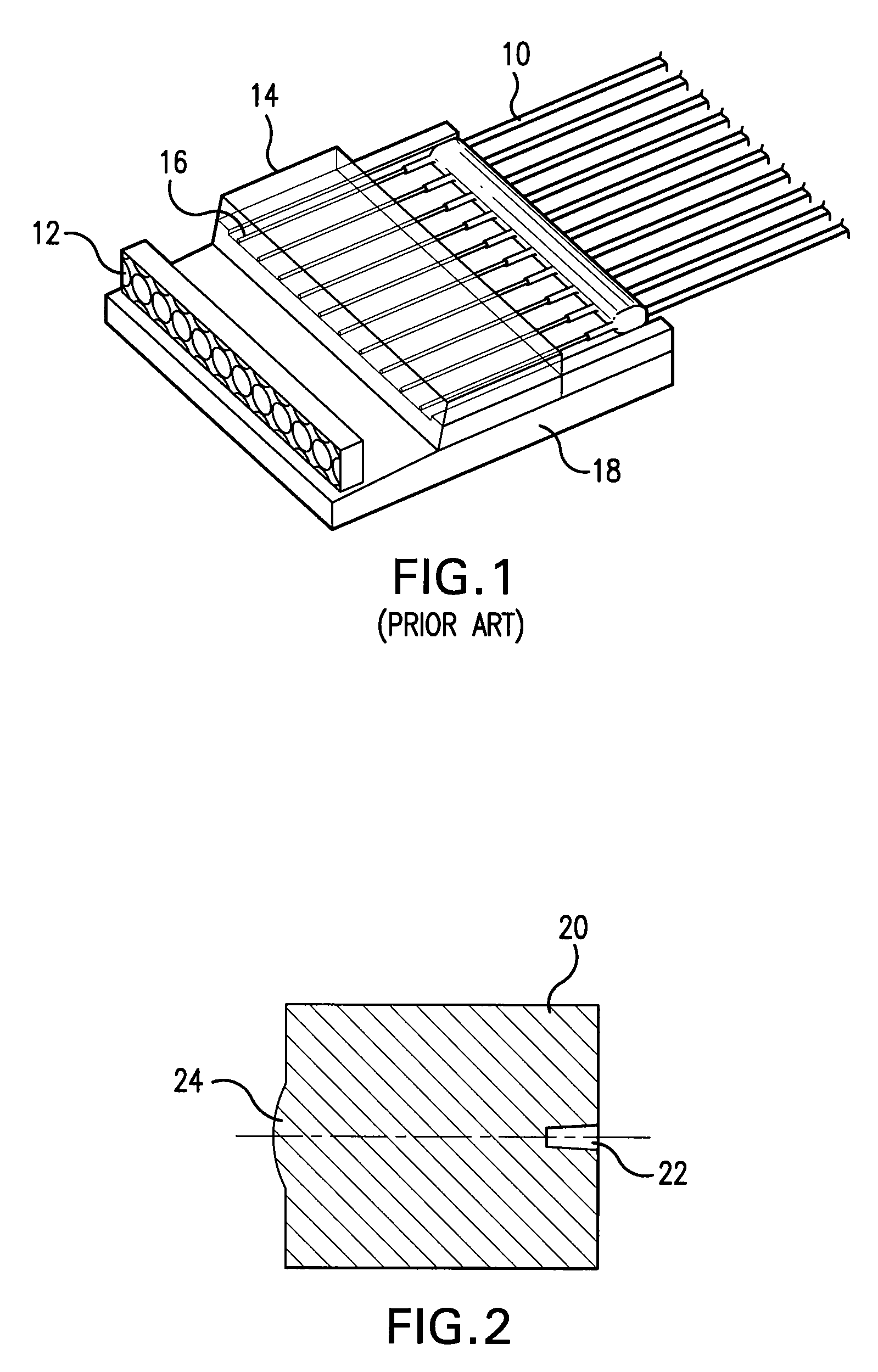
[0014] In any of the above-described collimator arrays, the depths of the holes are preferably arranged such that the optical distance between the end of a hole and the lens associated therewith is such that when a fiber is inserted to the end of the hole, the lens associated with the hole collimates light emitted from the end of the fiber and falling on the lens. In such cases, the optical distance between the end of the hole and the lens associated therewith is preferably made equal to the focal length of the lens. Alternatively and preferably, the depths of the holes may generally be arranged such that the optical distance between the end of a hole and the lens associated therewith is less than the focal length of the lens, such that the longitudinal position of the end of the fiber within the hole can be adjusted to adjust the collimation provided.

Problems solved by technology

However, the cost advantage may be lost using methods other than molding.

Method used


Image

  • Collimator array
  • Collimator array
  • Collimator array

Examples


Embodiment Construction

[0025] Reference is now made to FIG. 2 which illustrates schematically a cross sectional view of a transmissive collimator array according to one embodiment of the present invention, showing a single channel. The collimator transparent block 20 of this single channel preferably has a hole 22 into which the bare fiber is inserted, and a lens 24 aligned exactly opposite the lens.

[0026] Reference is now made to FIG. 3 which illustrates the single channel of the collimator array of FIG. 2 with an input fiber 32 attached. The depth of the hole in the collimator block 30 is arranged to be such that, when the fiber 32 is pushed to the bottom of the hole, the distance of the fiber end from the lens, taking into account the refractive index of the material of the device, is such that a collimated beam is output from the lens 34. Alternatively and preferably, since there may still be some element of inaccuracy even in a precision molded part, whether in dimensions or, more likely, in refract...


PUM


Abstract

A collimator array using a molded element to hold the input fibers and to collimate the light. The input fibers are held within holes in one face of the element, and the collimation of the light emitted from the ends of the fibers is performed by an array of lenses appropriately located such that each lens collimates the light emitted from a fiber end. The lateral spacing between the holes is made to be equal to the lateral spacing between the lenses of the array. Since, in a molded element, this lateral spacing can be accurately provided, good alignment of the input fibers with the lenses can be achieved. The depths of the holes can be made such that when a fiber is inserted right to the bottom of a hole, the end of that fiber is accurately located such that the light emitted therefrom is collimated by the lens. This avoids the need for accurate manual alignment of the fibers of the array. Alternatively, the hole can be made slightly deeper than this predetermined depth, to provide some adjustment in the lens-fiber distance for adjusting the level of collimation.

Description

[0001] This application claims priority from U.S. Provisional Patent Application Ser. No. 60 / 834,734 filed on Aug. 1, 2006, and which is incorporated herein by reference in its entirety.FIELD OF THE INVENTION [0002] The present invention relates to the field of fiber optical collimator arrays, especially for use in optical communication applications. BACKGROUND OF THE INVENTION [0003] Commonly found prior art collimator arrays, as typically shown in FIG. 1, generally use an input fiber array 10 and a lens array 12 constructed from separate elements, and mechanically aligned opposite each other, so that the light from each fiber impinges centrally on its associated lens. The fiber array itself commonly comprises a silicon V-groove mechanical structure 14 with a single mode, bare fiber 16, typically with a diameter of 125 μm, aligned and clamped by means of a cover plate inside each V-groove. Both V-groove structure 14 and lens array 12 are mounted on a base plate 18. The accuracy of ...

Claims


Application Information

Patent Timeline
Patent Type & Authority Applications(United States)
IPC IPC(8): G02B27/30
CPCG02B3/0031G02B3/005G02B3/0075G02B19/0014G02B27/0961G02B27/30G02B19/0057G02B5/08
Inventor COREM, YOSSICOHEN, GILFRENKEL, BORIS
Owner II VI DELAWARE INC
Why Eureka
Try Eureka