Light Pressure Rotator and Light Pressure Rotating Device

Inactive Publication Date: 2008-02-07
THE RITSUMEIKAN TRUST
View PDF1 Cites 27 Cited by
  • Summary
  • Abstract
  • Description
  • Claims
  • Application Information

AI Technical Summary

Benefits of technology

[0030] According to the light pressure rotator of claim 1, the light pressure rotator is light pressure trapped near the focus of the condensing irradiated light and is light pressure rotated about the central axis of rotation by condensing irradiating the light from above the upper surface. Since the reverse torque generating section is removed, faster light pressure rotation is achieved compared to the light pressure rotator not removed with the relevant section. Therefore, when the rotator is light pressure rotated in the medium such as micro-fluid, the surrounding micro-fluid is more efficiently stirred and mixed, and the rotary force of the light pressure rotator is increased.
[0031] According to the light pressure rotator of claim 2, the reverse torque generating section is a predetermined region on the central axis of rotation side of the third side face and the relevant section is removed, whereby the material cost is reduced by the removed section. The rotary force is increased by the reduced amount of the entire weight.
[0032] According to the light pressure rotator of claim 3, the light pressure rotator is light pressure trapped near the focus of the condensing irradiated light and is light pressure rotated about the central axis of rotation by condensing irradiating the light from above the upper surface. Furthermore, since the third side face is inclined at a predetermined angle with respect to the first side face, the total amount of optical torque generated from the third side face increases compared to t

Problems solved by technology

However, when the light pressure rotator arranged with a plurality of blades as described above is arranged in the medium consisting of liquid, the visco

Method used


Image

  • Light Pressure Rotator and Light Pressure Rotating Device
  • Light Pressure Rotator and Light Pressure Rotating Device
  • Light Pressure Rotator and Light Pressure Rotating Device

Examples


first embodiment

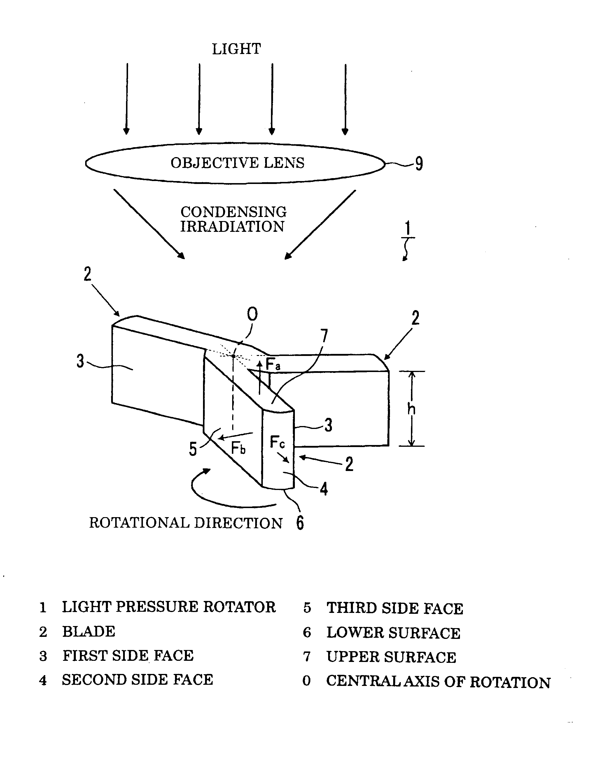
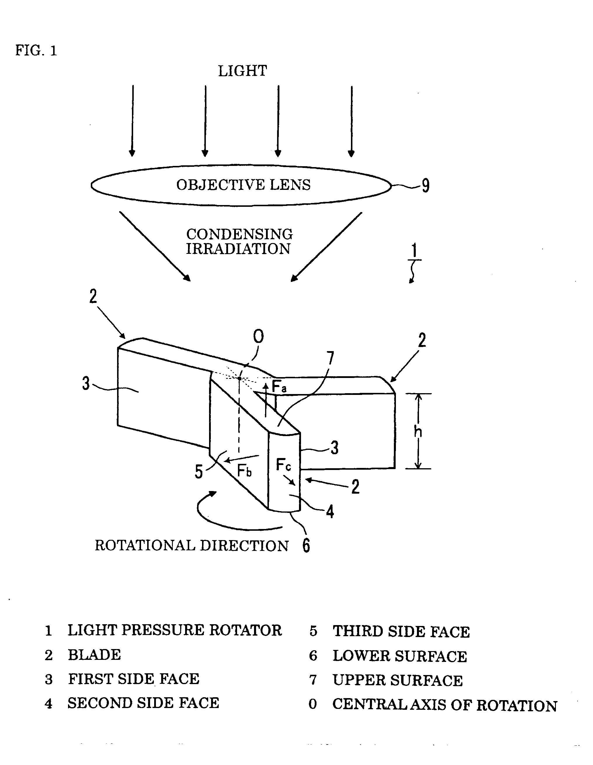
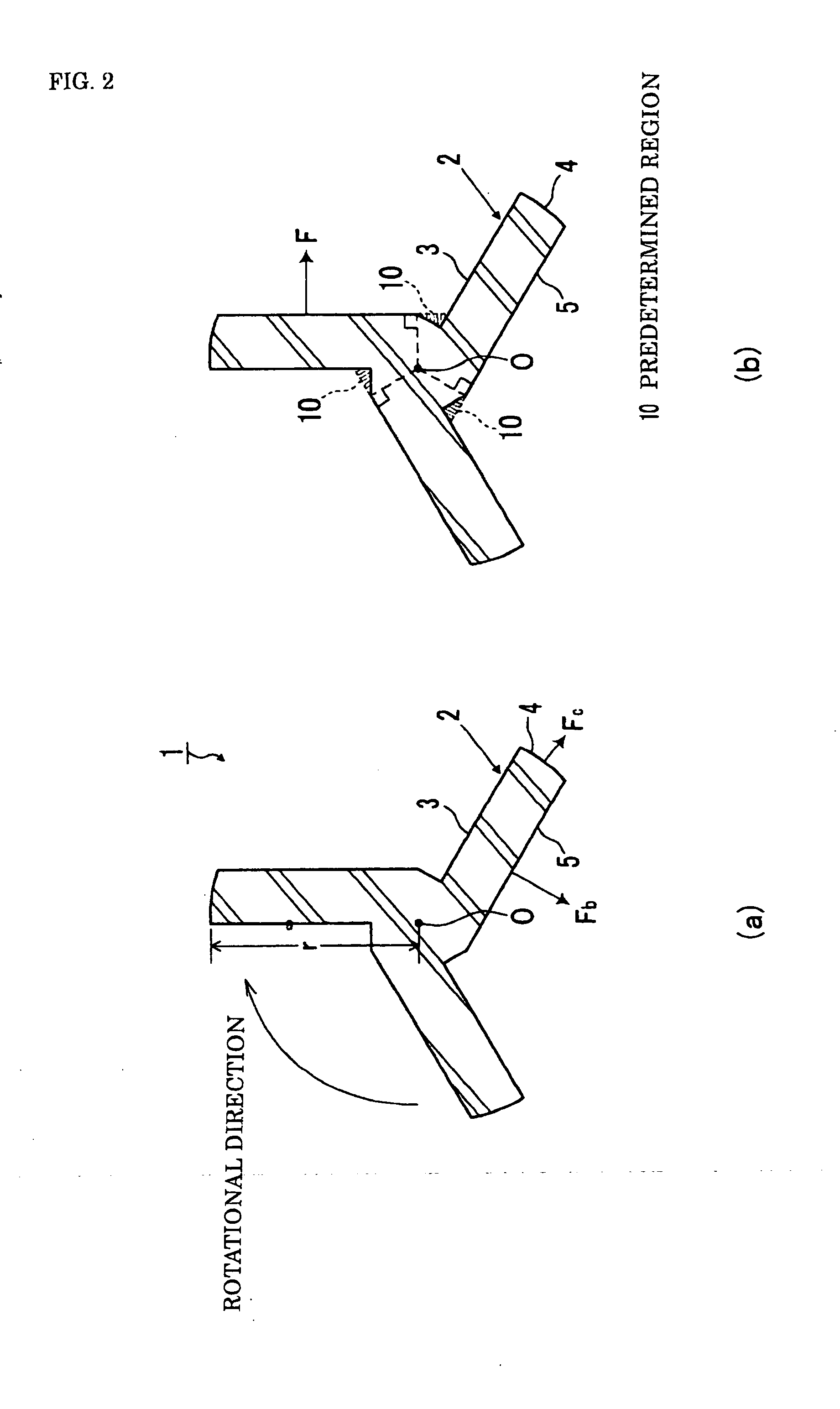
[0109] The light pressure rotator according to the embodiment of the present invention will now be described based on the figures. FIGS. 1 and 2 are views illustrating the light pressure rotator 1 effectively used in the optical mixer and the like according to the present invention. The high pressure rotating body 1 is a light pressure rotator being light pressure trapped by the light pressure generated by irradiation of light such as laser light and light pressure rotated about the central axis O of rotation, and is manufactured by micro-machine technique. The light pressure is the force generated, when the change in momentum in refraction and reflection of light is transformed as dynamic momentum to the microscopic object having light transmissivity, in the direction perpendicular to the surface. Therefore, the light pressure rotator 1 simply needs to have light transmissivity, and dielectric material such as transparent glass, organic substance such as PMMA (polymethyl methacryla...

fourth embodiment

[0133] A light pressure rotator 26 according to the present invention will now be described based on FIG. 6. The light pressure rotator 26 is a light pressure rotator being light pressure trapped by irradiation with light and light pressure rotated about the central axis O of rotation, and having four blades 28 radially arranged at equidistance with the central axis O of rotation as the center, each blade including a first side face 3 extending in the radial direction from the central axis O of rotation, a second side face 4 facing the central axis O of rotation, a third side face 5 facing the first side face 3, a lower surface 6 intersecting the central axis O of rotation, and a light pressure generating inclined surface 27 facing the lower surface 6 and inclined downward from the first side face 3 towards the third side face 5. The light pressure generating inclined surface 27 is a plane formed so as to contact the first side face 3, the second side face 4, and the third side face...

third embodiment

[0138] The light pressure generating curved surface 31 is a curved surface formed so as to contact the first side face 3, the second side face 4, and the third side face 5, as shown in the figure. Specifically, the light pressure generating curved surface is formed to a curved surface shape so that the angle formed by the radial direction passing through the central axis O of rotation and the light pressure direction is a right angle at each point on the light pressure generating curved surface 31. Thus, the optical torque expressed by the inner product of the light pressure generated from the light pressure generating curved surface (light pressure generating inclined surface) 31 and the distance from the central axis O of rotation increases and the total amount of optical torque becomes a maximum, compared to the light pressure rotator 26 of the third embodiment in which the light pressure generating inclined surface 27 is formed into a plane, whereby the light pressure rotator 30...


PUM


Abstract

The light pressure rotator (1) is the light pressure rotator being light pressure trapped by irradiation with light and light pressure rotating about the central axis O of rotation, characterized in that a reverse torque generating section generating a torque for rotating the rotator in the direction reverse to the predetermined direction is removed from a section arranged with three blades (2) each having a first side face (3) extending in the radial direction from the central axis O of rotation, a second side face (4) facing the central axis O of rotation, a third side face (5) facing the first side face (3), a lower surface (6) intersecting the central axis O of the rotation, and an upper surface (7) facing the lower surface (6). The light pressure rotating device comprises the light pressure rotator (1), a light source (C), and an objective (condenser) lens D.

Description

TECHNICAL FIELD [0001] The present invention relates to light pressure rotating bodies and light pressure rotating devices used in stirring micro-fluid and the like, more specifically, to a light pressure rotator and a light pressure rotating device that rotates with the light pressure generated by irradiation of light as driving source. BACKGROUND ART [0002] Conventionally, a mixer of a type in which magnetized stirring rotator is arranged at the bottom of a container accommodating liquid, and the stirring rotator is rotated by the rotatably driven magnet to stir the liquid is known for stirring the micro-fluid and so on (see e.g., patent document 1). However, such conventional mixer of the type driven by magnets will become impossible to use since the dimension of the microscopic flow path of an integrated chemical analysis equipment (micro-analysis chip) for mixing and reacting a very small amount of test solution and reagent to perform analysis is assumed to have a width of a fe...

Claims


Application Information

Patent Timeline
IPC IPC(8): B01F7/00
CPCB01F7/0025B01F13/0059B01F15/00435B01F15/00551Y02E10/46B81B2201/038F03G6/00F03G6/06F03G7/00B81B3/0029F03G7/005B01F27/112B01F33/30B01F35/3205B01F35/30Y02P70/10F03G7/016F03G6/089
Inventor UKITA, HIROO
Owner THE RITSUMEIKAN TRUST
Why Eureka
Try Eureka