Bidirectional transmission circuit and sending/receiving element

a transmission circuit and bidirectional technology, applied in the field of bidirectional transmission circuits, can solve the problems that the high-speed transmission of data suppressing signal reflection and the reduction of power consumption cannot be realized simultaneously, and achieve the effect of reducing power consumption and low power consumption

Inactive Publication Date: 2008-02-07
FUJITSU LTD
View PDF11 Cites 54 Cited by
  • Summary
  • Abstract
  • Description
  • Claims
  • Application Information

AI Technical Summary

Benefits of technology

[0022] According to the present invention, as described above, when the first sending / receiving element operates as a sending side, the first control unit cuts off the connection of the transmission bus to the first termination voltage source via the first terminating resistor by setting the connection by the first switch to off and the second control unit sets the connection of the transmission bus to the second termination voltage source via the second terminating resistor to on by setting the connection by the second switch to on; thus, data sending can be performed reliably without a signal from the first sending / receiving element to the second sending / receiving element being reflected even if the data sending from the first sending / receiving element to the second sending / receiving element is high-speed transmission using signals at high frequencies.
[0023] In addition, since, at this time, the first terminating resistor on the sending side of the transmission bus is cut off from the transmission bus by the first control unit and only the second terminating resistor on the receiving side of the transmission bus is connected to the transmission bus by the second control unit, an electric current flowing in the bidirectional transmission circuit caused by signal transmission from the first sending / receiving element to the second sending / receiving element can be made smaller than that by the conventional technique described with reference to the above FIG. 2, thereby realizing low power consumption.
[0024] That is, according to the present invention, high-speed transmission suppressing signal reflection and reduction of power consumption can be realized simultaneously.

Problems solved by technology

That is, according to the technique disclosed in Japanese Patent Application Laid-Open No. 10-20974 described above, high-speed transfer of data suppressing signal reflection and reduction of power consumption cannot be realized simultaneously.

Method used


Image

  • Bidirectional transmission circuit and sending/receiving element
  • Bidirectional transmission circuit and sending/receiving element
  • Bidirectional transmission circuit and sending/receiving element

Examples


Embodiment Construction

[0027] An embodiment of the present invention will be described below with reference to drawings.

[1] An Embodiment of the Present Invention

[0028] [1-1] Configuration

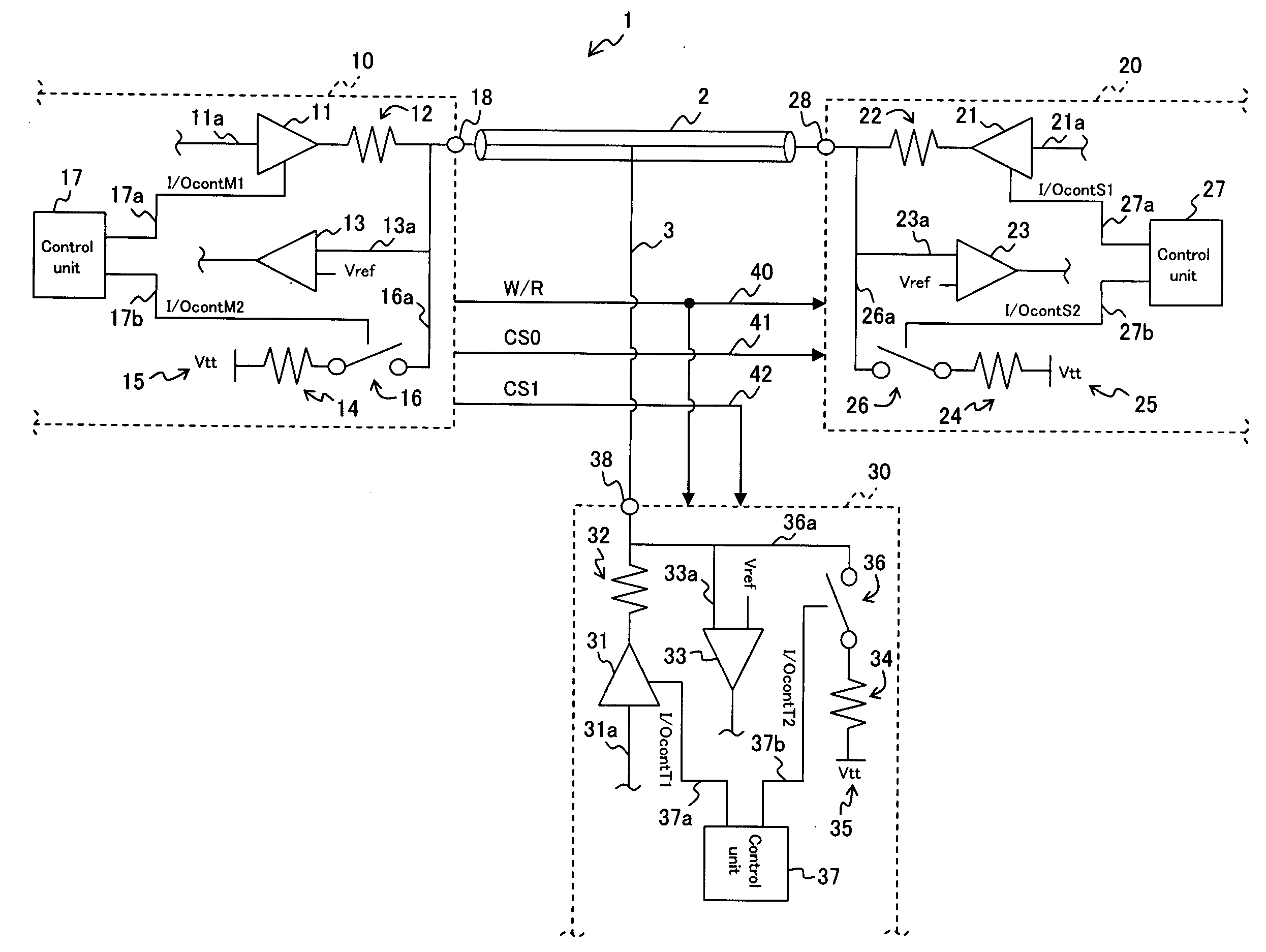
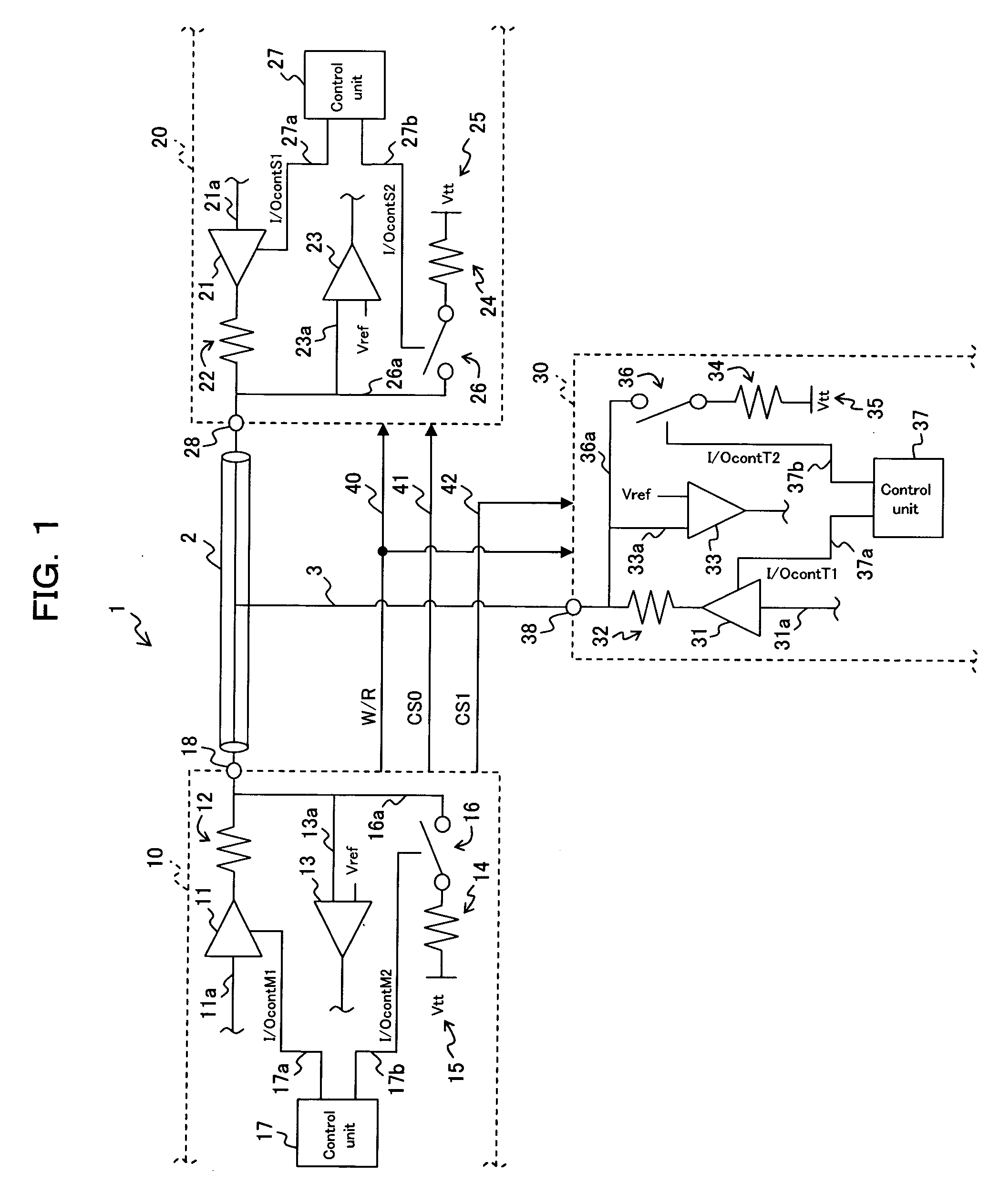
[0029] First, a configuration of a bidirectional transmission circuit 1 as an embodiment of the present invention will be described with reference to FIG. 1.

[0030] As show in FIG. 1, a bidirectional transmission circuit 1 is comprised of a transmission bus 2, a signal line 3, a first sending / receiving element 10, a second sending / receiving element 20, a third sending / receiving element 30, a Write / Read signal line (hereinafter referred to as a control signal line) 40, a first CS (Chip Select) signal line 41, and a second CS signal line 42.

[0031] The transmission bus 2 transmits (transfers) signals (data) in both directions.

[0032] The first sending / receiving element 10 is an element (chip; for example, the CPU (Central Processing Unit) side) connected to one end of the transmission bus 2 to operate as a main control ...


PUM


Abstract

According to the present invention, in order to simultaneously realize high-speed transmission suppressing signal reflection and reduction of power consumption, a bidirectional transmission circuit, in which a plurality of sending/receiving elements send and receive signals via a transmission bus, is constructed so that, when a first sending/receiving element operates as a sending side, a first control unit sets a connection of the transmission bus to a first termination voltage source via a first terminating resistor by a first switch to off and a second control unit sets a connection of the transmission bus to a second termination voltage source via a second terminating resistor by a second switch to on.

Description

BACKGROUND OF THE INVENTION [0001] 1) Field of the Invention [0002] The present invention relates to a bidirectional transmission circuit of SSTL (Stab Series Terminated Logic) in which a plurality of sending / receiving elements mutually send and receive a signal via a transmission bus. [0003] 2) Description of the Related Art [0004]FIG. 2 shows a configuration of a conventional SSTL (Stab Series Terminated Logic) bidirectional transmission circuit (hereinafter referred to simply as a transmission circuit) 100. As shown in FIG. 2, the conventional transmission circuit 100 comprises a transmission bus 101 for transferring a signal, a first sending / receiving element 110 and a second sending / receiving element 120 that can mutually send and receive a signal via the transmission bus 101, a signal line 102 for sending a Write / Read signal (sending / receiving switching signal) from the first sending / receiving element 110 to the second sending / receiving element 120, a terminating resistor 132 ...

Claims


Application Information

Patent Timeline
Patent Type & Authority Applications(United States)
IPC IPC(8): H04J15/00H04J99/00
CPCH04L25/0278H04L5/1469
Inventor FUKUDA, TAKATOSHI
Owner FUJITSU LTD
Why Eureka
Try Eureka