
Sump pump control system

a control system and pump technology, applied in the direction of pump control, pump control, positive displacement liquid engine, etc., can solve the problems of system not allowing the configuration and control of more than one pump, system not allowing the use of submerged ac sump pump or backup pump, system not allowing for plurality of pumps to operate from the same power source, etc., to achieve a high level of security

Inactive Publication Date: 2008-02-07
LITTWIN KENNETH M +2
View PDF15 Cites 63 Cited by
  • Summary
  • Abstract
  • Description
  • Claims
  • Application Information

AI Technical Summary

Benefits of technology

"The invention is a pump control unit that can be powered by either utility AC power or battery DC power in case of AC power loss. The DC power is supplied by a plurality of sealed lead acid batteries. The pump control unit has several visual and audio indicators for normal and abnormal pump operation, including AC power lights, DC power lights, primary mode lights, secondary mode lights, audio alarm for overload for each pump, pump control unit overheat, low battery A, low battery B, check primary pump, check secondary pump, and the battery charging status. The total battery voltage is displayed with digital voltmeter. Battery charging circuit and inverter overload protection are included. The control will function with a single pump in the absence of a secondary pump. Pump switching circuitry monitors pumps for malfunctions and switches operation accordingly, as well as alternating pump usage under normal conditions to protect against damage than can be caused by an extended idle state. Three float switches provide a high level of security."

Problems solved by technology

Previously, control systems do not allow for a plurality of pumps to operate from the same power sources.
The system does not allow for configuration and control of more than one pump.
The system does not allow for the use of submersible AC sump pump or backup pump.
Additionally, sump pumps that remain idle can be subject to damage from humidity, corrosion, or blockage.

Method used


Image

  • Sump pump control system
  • Sump pump control system
  • Sump pump control system

Examples


Embodiment Construction

Operation of System:

[0032]The pump operation is established with one pump as a backup pump and a pair of lead acid batteries as a backup power supply. The pump control unit serves as replacement for the utility power, in the case of AC power loss and is active for battery power as well. The control unit serves also as an alternative energy device that replaces gas-fueled generators. It is equipped with advanced pump switching logic to accommodate for normal and abnormal pump operation. The pump switching and pump control logic is active for battery power as well as AC power mode.

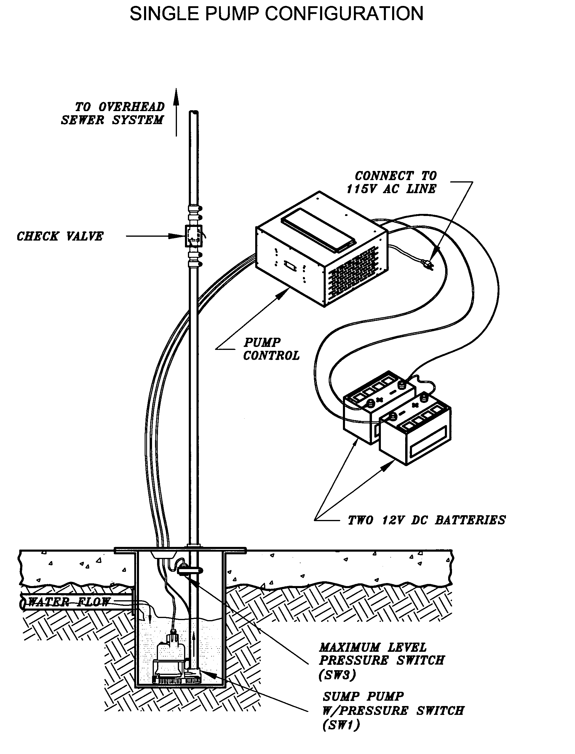
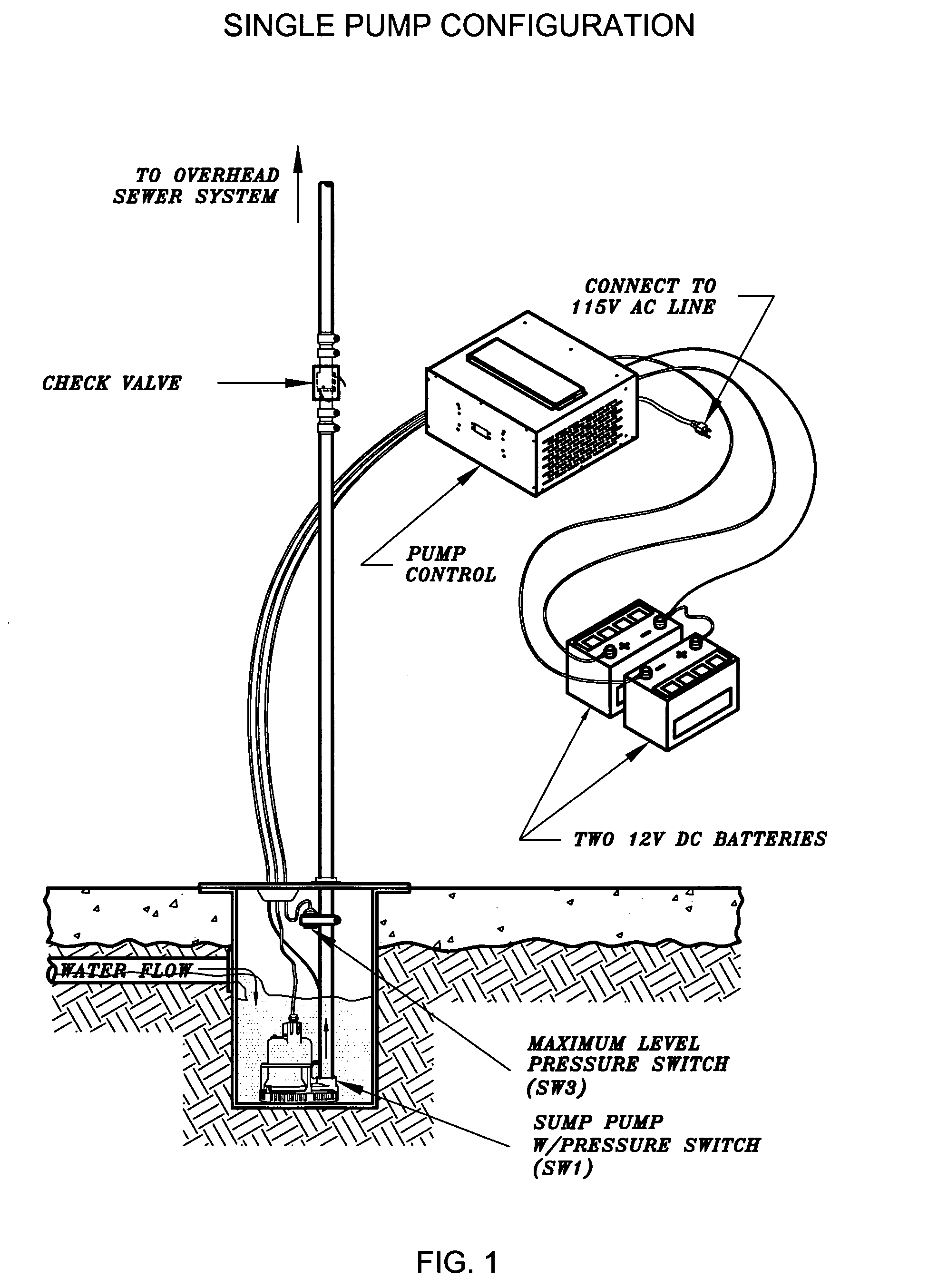
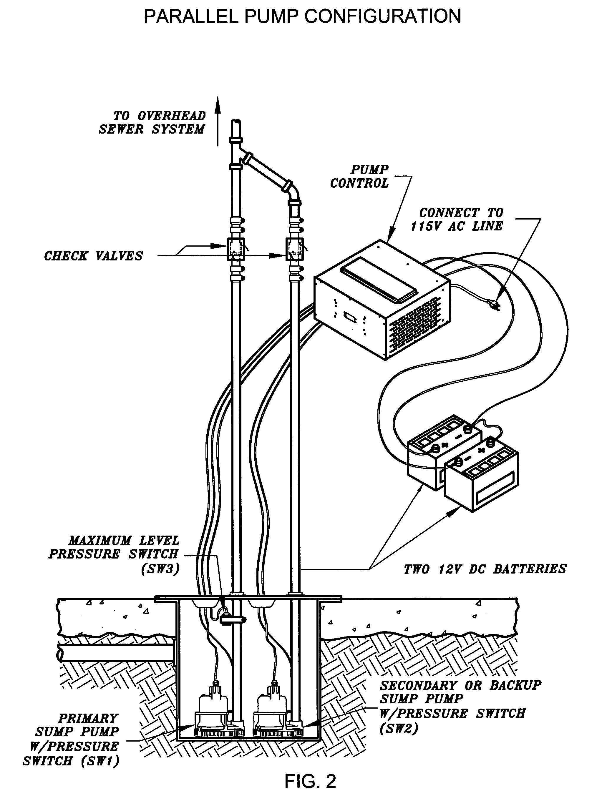
[0033]The pump control unit operates in 3 modes; the user has the option to choose between the 3 modes:[0034]1. Single pump configuration (utilizes 100% of the pump operation) (FIG. 1)[0035]2. Double pump in parallel configuration (utilizes 50% duty of each pump) (FIG. 2)[0036]3. Double pump in staggered configuration (utilizes 80% duty of primary and 20% duty of secondary pump). (FIG. 3)

[0037]Each pump has ...


PUM


Abstract

A sump pump control system for monitoring and driving AC pumps that are supplied by directly either by AC utility power, or converted DC battery power. AC power is continuously monitored and the control automatically switches to DC battery supply in the case of power failure. DC battery power is converted to AC power. The control is equipped with unique pump switching circuitry allowing the pumps to be configured in parallel or staggered positions. Both pumps automatically alternate to prevent damage to pumps from humidity and corrosion that can result from remaining idle. Each pump has its own float switch to control operation. A third float switch controls both pumps in case of failure of either pump or float switch. Multiple visual and audio signals are included, displaying present power and pump conditions as well as alerting to any pump malfunction. The control utilizes two 12 volt deep cycle lead acid batteries that are being monitored for voltage level and continuously trickle charged to maintain maximum capacity. Batteries can be paralleled to obtain longer pump running time when AC power fails. The control system also allows for use of a single pump in the absence of a second pump.

Description

CROSS REFERENCE TO RELATED APPLICATIONS[0001]This application claims the benefit of PPA Ser. No. 60 / 779,333, filed Mar. 3, 2006 by the present inventor(s).FEDERALLY SPONSORED RESEARCH[0002]Not applicableSEQUENCE LISTING OF PROGRAM[0003]Not applicableBACKGROUND OF INVENTION[0004]1. Field of Invention[0005]This invention generally relates to a pump control system, specifically a sump pump control unit which controls a plurality of alternating AC sump pumps operated by either AC power or inverted battery DC power.[0006]2. Prior Art—Objects and Disadvantages[0007]This invention monitors power and pump conditions, automatically triggering controlled alerts and responses. Both power and mechanical pump status are continuously visually displayed. Pump mechanical malfunctions are visually displayed and alerted audibly.[0008]Previously, control systems do not allow for a plurality of pumps to operate from the same power sources. In these systems, the primary and backup pumps are driven by di...

Claims


Application Information

Patent Timeline
Patent Type & Authority Applications(United States)
IPC IPC(8): F04B17/03
CPCF04B49/025F04B47/06
Inventor LITTWIN, KENNETH M.BACCHIERE, DANIEL P.KAHRIMANOVIC, ELVIR
Owner LITTWIN KENNETH M
Learn More