

Membrane-Electrode Assembly For Fuel Cell
a fuel cell and membrane electrolectrode technology, applied in the field of membrane electrolectrode assembly for fuel cells, can solve the problems of insufficient catalytic activity, insufficient catalytic activity, poor cell performance (initial stage performance and steady state performance), etc., and achieve excellent durability and catalytic performance. , the effect of drainag
- Summary
- Abstract
- Description
- Claims
- Application Information
AI Technical Summary
Benefits of technology
Problems solved by technology
Method used
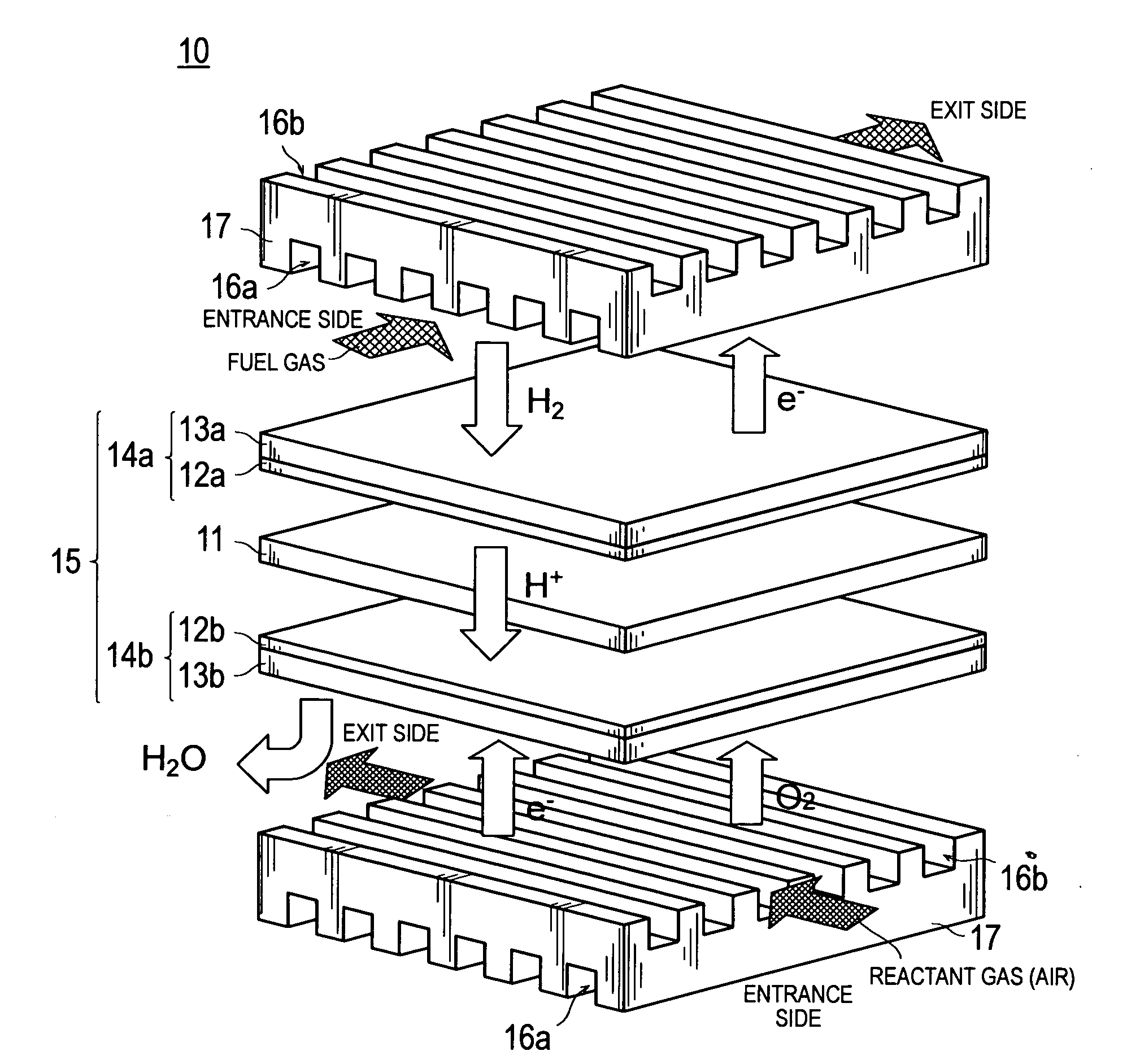
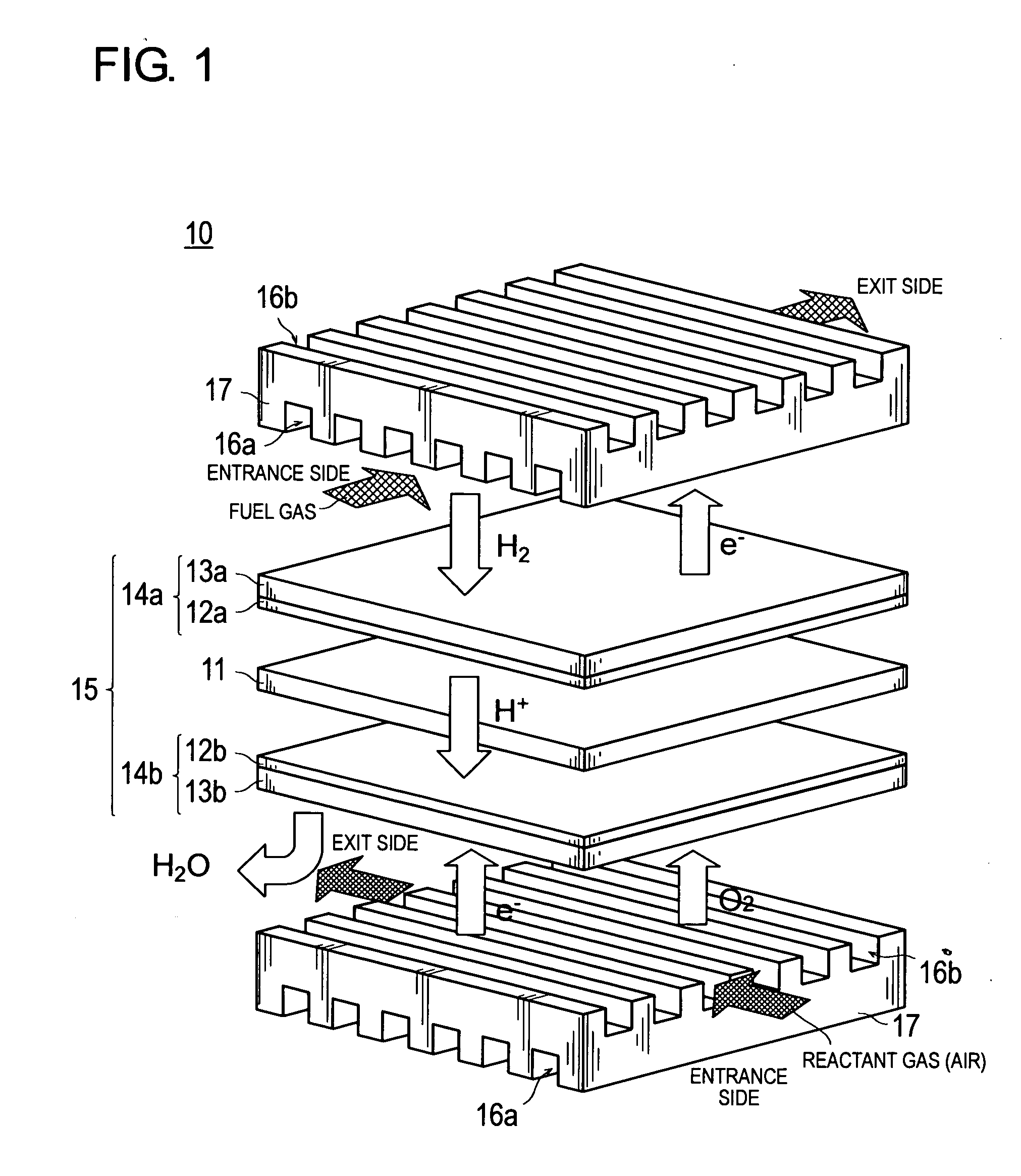
Image

Examples
example 1
[0102] MEA was carried out according to the following procedure.
[0103] 150 g of the catalyst 1, 50 g of the catalyst 3, Nafion in the same amount as carbon, purified water and isopropyl alcohol were added and sufficiently dispersed with a homogenizer, and further subjected to a defoaming operation to prepare the catalyst slurry (B1).
[0104] This slurry was printed in specified amount on one surface of carbon paper (“TGP-H” produced from Toray Corp.), which was the gas diffusion layer (GDL), by a screen printing method, and dried at 60° C. for 24 hours.
[0105] Subsequently, 50 g of the catalyst 1, 150 g of the catalyst 3, 2000 g of a 5% Nafion solution (“DE-520” produced from DuPont Co., Ltd.: EW=1000) containing Nafion in the same amount as carbon, purified water and isopropyl alcohol were added and sufficiently dispersed with a homogenizer, and further subjected to a defoaming operation to prepare the catalyst slurry (A1). This slurry was printed in specified amount on the carbon ...
example 2
[0108] 150 g of the catalyst 1, 50 g of the catalyst 4, Nafion in the same amount as carbon, purified water and isopropyl alcohol were added and sufficiently dispersed with a homogenizer, and further subjected to a defoaming operation to prepare the catalyst slurry (B2).
[0109] This slurry was printed in specified amount on one surface of carbon paper, which was the gas diffusion layer, by a screen printing method, and dried at 60° C. for 24 hours.
[0110] Subsequently, 50 g of the catalyst 1, 150 g of the catalyst 4, 2000 g of a 5%-Nafion solution containing Nafion in the same amount as carbon, purified water and isopropyl alcohol were added and sufficiently dispersed with a homogenizer, and further subjected to a defoaming operation to prepare the catalyst slurry (A2). This slurry was printed in specified amount on the carbon paper, already coated with the catalyst slurry (B2), by a screen printing method, and dried at 60° C. for 24 hours.
[0111] A cathode catalyst layer was prepar...
example 3
[0112] 150 g of the catalyst 1, 50 g of the catalyst 5, Nafion in the same amount as carbon, purified water and isopropyl alcohol were added and sufficiently dispersed with a homogenizer, and further subjected to a defoaming operation to prepare the catalyst slurry (B3).
[0113] This slurry was printed in specified amount on one surface of carbon paper, which was the gas diffusion layer, by a screen printing method, and dried at 60° C. for 24 hours.
[0114] Subsequently, 50 g of the catalyst 1, 150 g of the catalyst 5, 2000 g of a 5%-Nafion solution containing Nafion in the same amount as carbon, purified water and isopropyl alcohol were added and sufficiently dispersed with a homogenizer, and further subjected to a defoaming operation to prepare the catalyst slurry (A3). This slurry was printed in specified amount on the carbon paper, already coated with the catalyst slurry (B3), by a screen printing method, and dried at 60° C. for 24 hours.
[0115] A cathode catalyst layer was prepar...
PUM
| Property | Measurement | Unit |
|---|---|---|
| temperature | aaaaa | aaaaa |
| temperature | aaaaa | aaaaa |
| temperature | aaaaa | aaaaa |
Abstract
Description
Claims
Application Information