
Architectural Fabric

a technology of architectural fabric and fabric, applied in the field of architectural fabric, can solve the problems of unsuitable flexibility, fabric cannot be used efficiently, uv light tends to degrade and weaken fabric, etc., and achieve the effect of high seam strength

Active Publication Date: 2008-02-07
WL GORE & ASSOC INC
View PDF15 Cites 16 Cited by
  • Summary
  • Abstract
  • Description
  • Claims
  • Application Information

AI Technical Summary

Benefits of technology

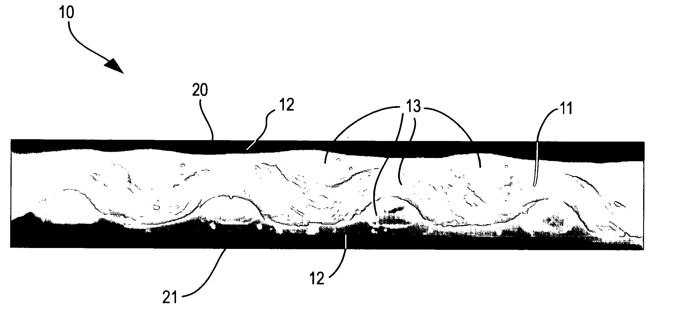
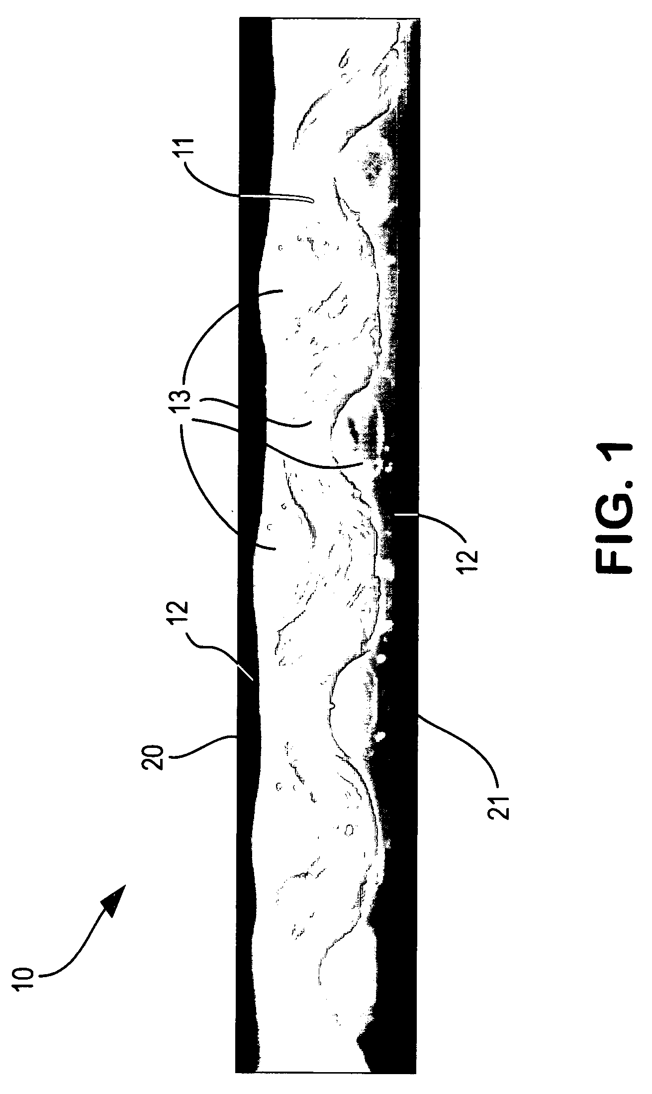
[0010] The present invention provides an article consisting of (a) a layer of fabric having a first surface and a second surface made of polytetrafluoroethylene fibers; and (b) a fluoropolymer coating disposed on said first surface of said fabric. In another embodiment, the invention further includes a fluoropolymer coating disposed on the second surface of the fabric. The fluoropolymer coating is preferably THV. The article of the present invention is preferably waterproof, fire retardant, and has high seam strength. It is also preferably an architectural fabric for retractable, temporary, or permanent structures, such as tensile structures, and is adapted to be joined to itself by welding.

Problems solved by technology

UV light tends to degrade and weaken fabric over time.
Although this product has certain desirable qualities, it is not suitably flexible.
The fabric thus cannot be used efficiently in applications where convenient removal of the fabric is needed.
These products have flexibility but only limited durability.
Unless specially treated, these fabrics are flammable and tend to degrade under UV light.
After a certain amount of flexing and UV exposure, these products develop cracks or other imperfections that allow water to penetrate the fabric at the point where it has been compromised.
Addition of the film requires additional processing, however.
A limitation of known architectural fabrics made of polytetrafluoroethylene fiber is that certain substances can be absorbed through wicking into the polytetrafluoroethylene fiber.
Once liquids are absorbed into the fibers of the fabric, undesirable color and / or light transmission variations can result.

Method used


Image

  • Architectural Fabric
  • Architectural Fabric
  • Architectural Fabric

Examples


example

An architectural fabric was prepared as follows:

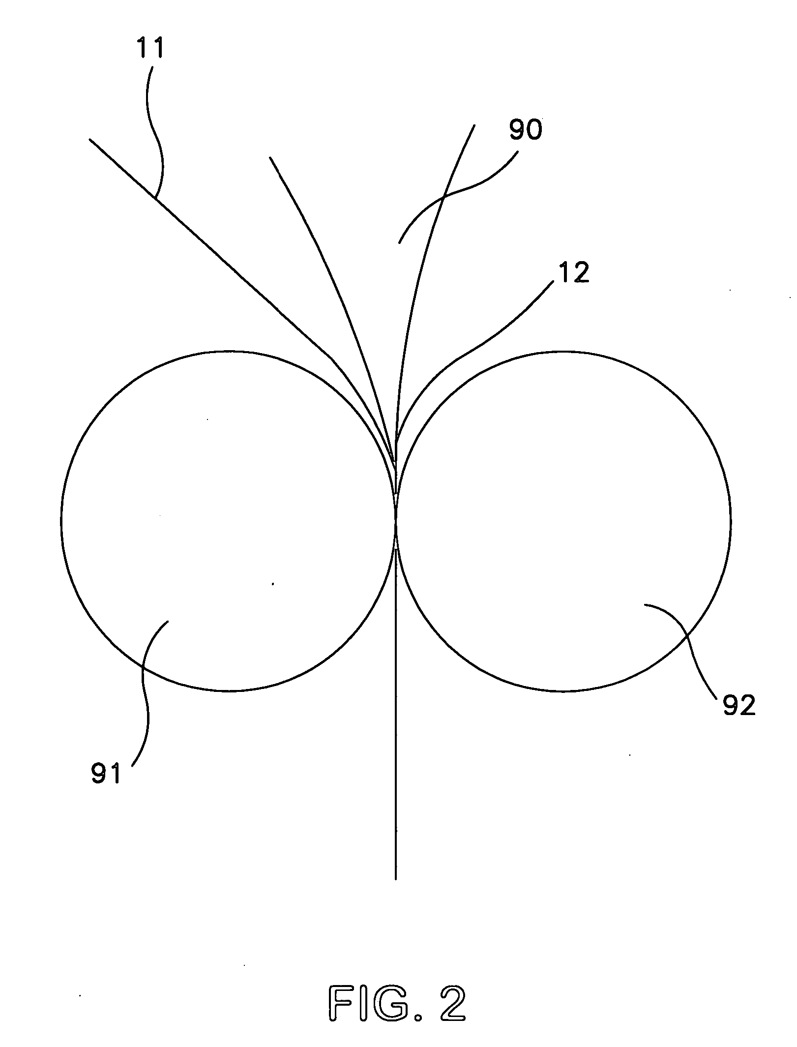
[0034] THV220 (Dyneon, Inc, Oakdale, Minn.) which was pigmented tan was extruded using a single screw extruder and a slotted die at a temperature of 250 C. It was directed vertically downward into a nip created by two rolls; one being a TEFLON® -sleeved EPDM rubber roll and the other a TEFLON®-coated steel roll. The thickness of the extruded film was 175 micrometers. The EPDM roll had a surface temperature of 90 C, and the steel roll had a surface temperature of 115 C. The surface speed of the rolls was 2.75 meters per minute. Fabric woven of expanded PTFE fiber was obtained from W.L. Gore & Associates, Inc. This fabric was woven in a plain weave, 18 ends by 18 picks per centimeter. Each end and each pick yarn was composed of two 500 denier expanded PTFE fibers plied together.

[0035] The fabric entered the nip over the steel roll and was pressed against the molten THV220 in the nip. The nip force was 130 Newtons per centimeter. The T...

example a

Densified Fiber

[0111] A fabric was woven from 1400 denier expanded PTFE fiber. The fabric is a plain weave with 18 ends by 18 picks per centimeter. This fiber is commercially produced by W.L. Gore & Associates, Elkton Md. USA and is identified as Gore part number M1000KTR. This fiber was produced according to the process of U.S. Pat. No. 6,071,452. The fiber produced by this process is translucent in appearance resulting from the densification of the fiber inherent with this process. The density of this fiber is approximately 2.2 grams per cubic centimeter as compared to the density of the fiber in the Comparative Example, which was approximately 1.5 grams per cubic centimeter. The optical transmission of the fabric of this Densified Fiber Example was 66%. When the fabric was exposed to the isopropyl alcohol as in the example above, the optical transmission increased to 69%, and the exposed area appeared visually very similar to the unexposed areas. Application of the isopropyl alc...

example b

Fiber with Filler

[0112] A fabric was woven from expanded PTFE fiber which contained a titianium dioxide pigment approximately 2.0% by weight, produced as taught in Example 1 of U.S. Pat. No. 5,262,234 (except TiO2 was used instead of a conductive filler and the widths adjusted to produce the desired denier). The fabric was a plain weave 18 ends by 18 picks per centimeter with each end and pick composed of two 500 denier expanded PTFE fibers, each fiber filled with a titanium dioxide pigment approximately 2% by weight, plied together. The optical transmission of the fabric measured to be 24%. When the fabric was exposed to the isopropyl alcohol as in the examples above, the optical transmission increased to 27%, and the exposed area appeared visually very similar to the unexposed areas. Application of the isopropyl alcohol thus increased the optical transmission by only 3%, a marked and surprising improvement over the Comparative Example.


PUM

PropertyMeasurementUnit
thicknessaaaaaaaaaa
thicknessaaaaaaaaaa
RHaaaaaaaaaa

Abstract

An article useful as an architectural fabric consisting of (a) a layer of fabric having a first surface and a second surface made of expanded polytetrafluoroethylene fibers that are densified or contain a filler or both; and (b) a fluoropolymer coating disposed on at least the first surface of the fabric.

Description

RELATED APPLICATIONS [0001] This application is a continuation-in-part of pending U.S. application Ser. No. 11 / 195,911, filed Aug. 2, 2005.FIELD OF INVENTION [0002] The present invention relates to fabric and, more particularly, to architectural fabric that is waterproof, fire retardant, flexible, durable, and aesthetically pleasing. BACKGROUND OF INVENTION [0003] Architectural fabric is fabric used as a building structure or part of a building structure. It typically provides protection for humans from elements such as wind, sun, and rain. It may be a permanent structure or a temporary one. If temporary, it may be retractable or removable, for example by folding, rolling, or otherwise storing. [0004] There are several requirements for architectural fabric. It must be strong enough to withstand wind and other stresses during assembly and use. It must be flexible and durable, so that it can be folded or rolled and its strength and integrity are maintained over time. It must be UV lig...

Claims


Application Information

Patent Timeline
Patent Type & Authority Applications(United States)
IPC IPC(8): B32B5/02B32B27/06
CPCY10S428/913B32B27/12Y10T442/2238Y10T442/2123Y10T442/20Y10T442/2631Y10T442/2213Y10T442/2115Y10T442/2221
Inventor KELMARTIN, THOMASRUSCH, GREG
Owner WL GORE & ASSOC INC
Learn More