Computer-assisted surgery tools and system

Active Publication Date: 2008-02-07
ORTHOSOFT ULC
View PDF16 Cites 246 Cited by
  • Summary
  • Abstract
  • Description
  • Claims
  • Application Information

AI Technical Summary

Benefits of technology

[0010] It is a further aim of the present invention to provide a novel positioning frame for adjusting a position and orientation of bone-altering tools in computer-assisted surgery.

Problems solved by technology

One of the issues pertaining to the efficiency of CAS is the creation of frames of references and the digitization of bone models.
In such cases, a plurality of points are digitized on the bone elements intraoperatively, which represents a time-consuming operation.

Method used


Image

  • Computer-assisted surgery tools and system
  • Computer-assisted surgery tools and system
  • Computer-assisted surgery tools and system

Examples


Embodiment Construction

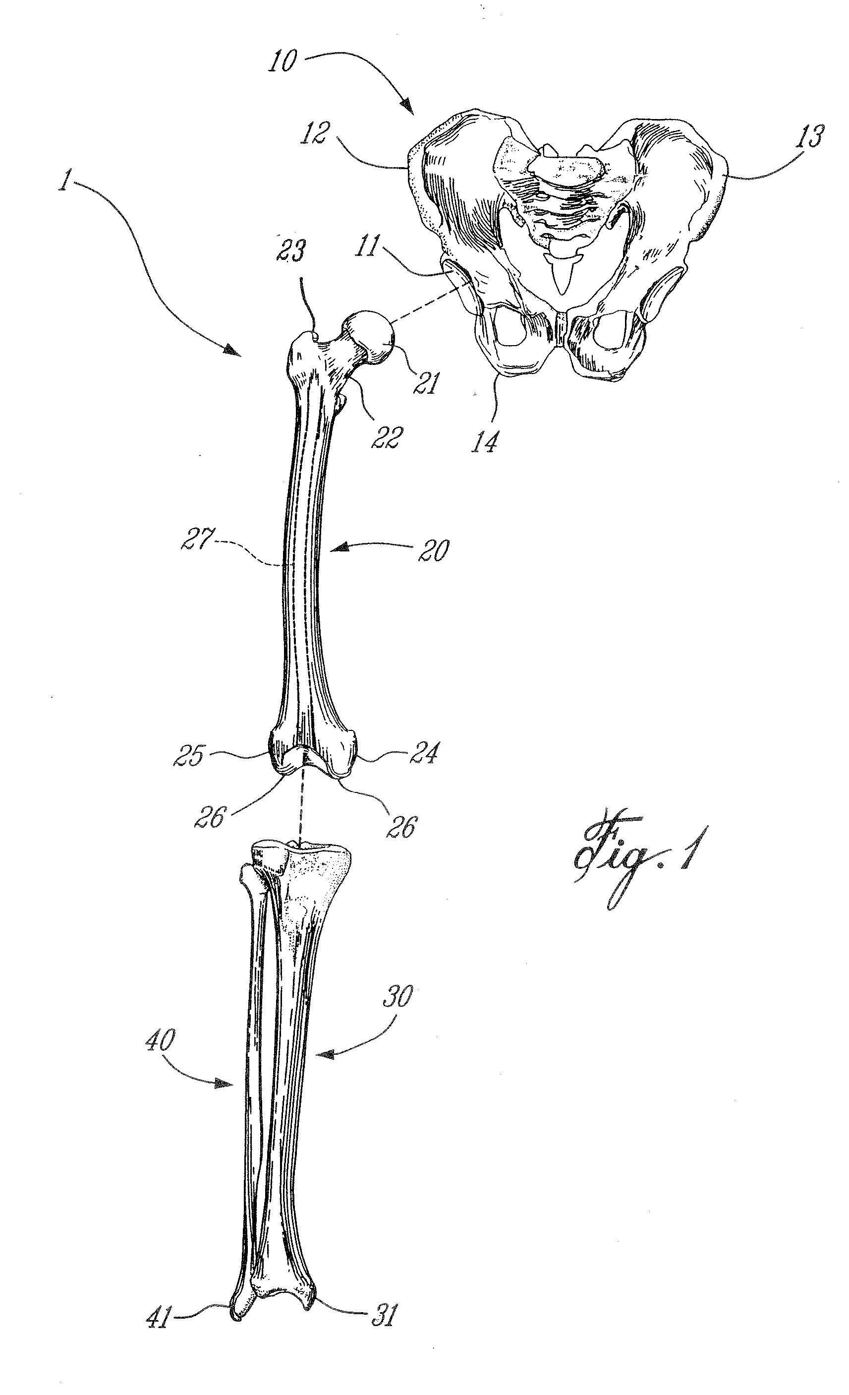
[0021] According to the drawings, and more particularly to FIG. 1, bones of the leg that will be involved in the hip replacement surgery of the present embodiment are generally shown at 1. FIG. 1 is provided as reference for the description of the steps of the hip replacement surgery method described herein. The bones are the pelvis 10, the femur 20, the tibia 30 and the fibula 40. Hereinafter, parts of these bones will each be referenced by numerals from the same numeric decade. For instance, parts of the pelvis (e.g., the acetabulum 11) will bear reference numerals between 11 and 14.

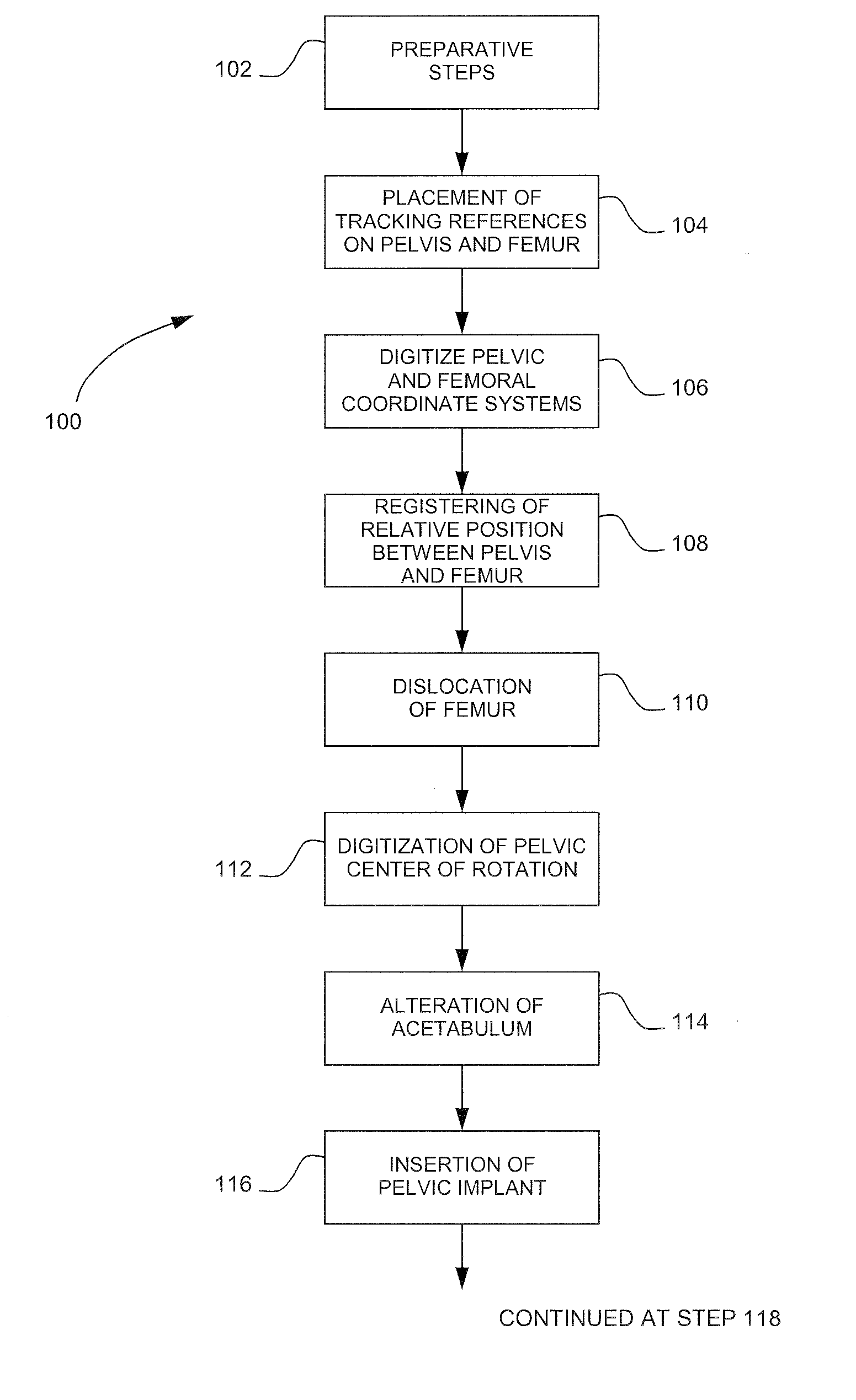
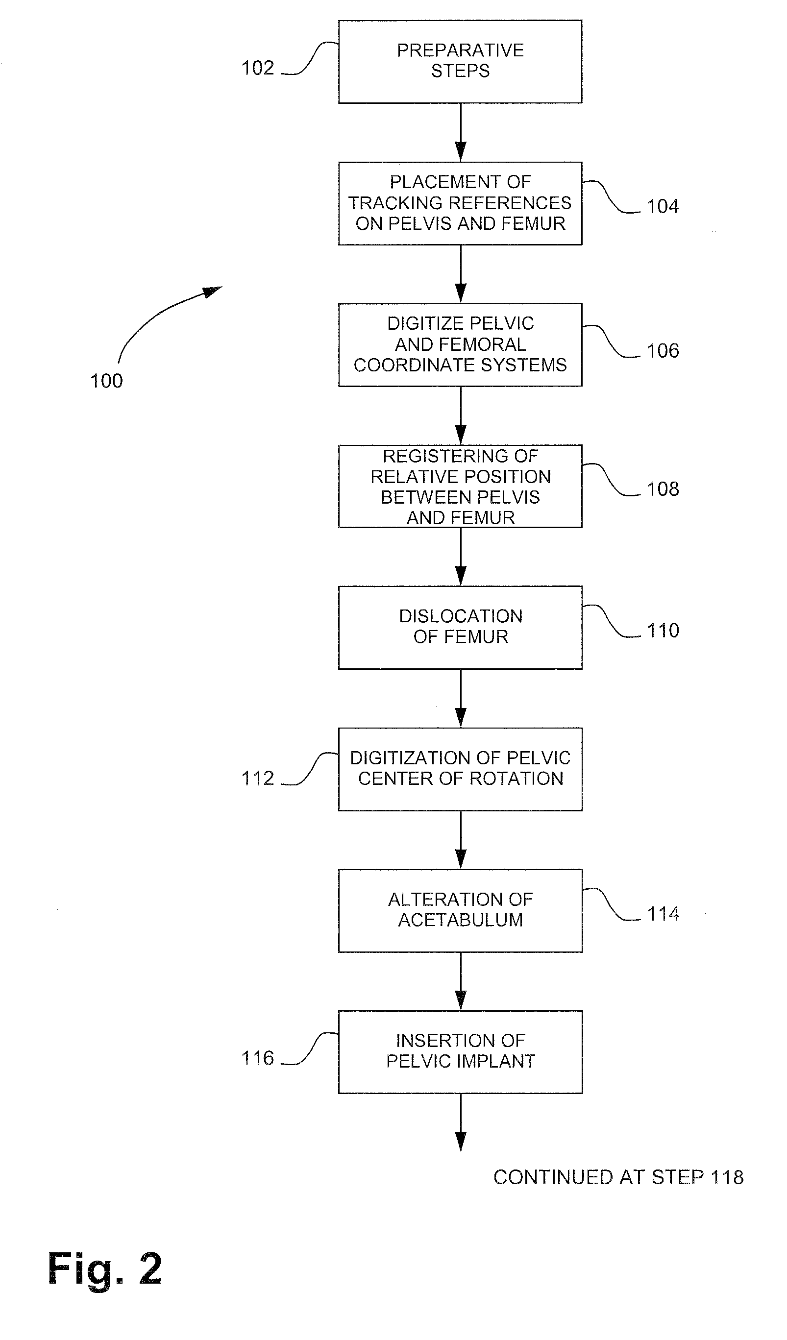
[0022] Referring to FIG. 2, a method for hip joint resurfacing surgery in accordance with the present embodiment is generally shown at 100. Although the method 100 is referred to in the singular, various choices of procedure will be given to the surgeon, as will be set forth in the forthcoming description, according to the preferences of the surgeon. A plurality of sequences can be derived from the me...


PUM


Abstract

A surface digitizing tool has a film of micro-sensor elements, with each micro-sensor element related in a network affected by a shape of the film. The film is flexible to conform to a shape of a selected surface of an object. A processing unit receives signals from the micro-sensor elements of the network. The processing unit has a model generator producing a model of the selected surface of the object from the signals of the network of resistive elements. A positioning frame aligns a position and orientation of a drilling tool with respect to a bone element.

Description

CROSS-REFERENCE TO RELATED APPLICATION [0001] This patent application claims priority on U.S. Provisional Patent Application No. 60 / 821,331, filed on Aug. 3, 2006. This patent application incorporates by reference U.S. patent application Ser. No. 11 / 339,499, by the present assignee, published as United States Publication No. 2006 / 0189864.FIELD OF THE APPLICATION [0002] The present application generally relates to Computer Assisted Surgery (CAS) such as hip joint resurfacing surgery and, more precisely, to a method for assisting hip joint resurfacing surgery and like orthopaedic surgery with CAS systems. BACKGROUND OF THE APPLICATION [0003] Orthopaedic surgery is constantly evolving to lessen the effects of surgery on patients. In order to reduce the amount of post-surgical pain, new methods and tools have been developed in CAS to minimize the invasiveness of surgery. Moreover, CAS systems constantly involve new features to accelerate surgeries. [0004] Also, CAS is more commonly used...

Claims


Application Information

Patent Timeline
IPC IPC(8): A61B17/16A61B17/17A61B5/05
CPCA61B5/1077A61B5/4504A61B5/4528A61B17/1746A61B17/175A61B19/201A61B2562/046A61B2019/502A61B2019/505A61B2019/508A61B2019/5255A61B2019/5265A61B2562/02A61B19/5244A61B34/20A61B90/11A61B2034/102A61B2034/105A61B2034/108A61B2034/2055A61B2034/2065
Inventor AMIOT, LOUIS-PHILIPPESZMUTNY, ERICMALETTE, LOUIS
Owner ORTHOSOFT ULC
Why Eureka
Try Eureka