Ferromagnetic tunnel junction structure, and magneto-resistive element and spintronics device each using same

a tunnel junction and magnetoresistive element technology, applied in the field of ferromagnetic tunnel junction structure, can solve the problems of difficult to obtain high-quality tunnel junctions, unsuitable alox amorphous barriers, uneven properties, etc., and achieves the effect of increasing tmr, ensuring high-quality tunnel junctions, and increasing quality

Active Publication Date: 2012-04-19
NAT INST FOR MATERIALS SCI
View PDF3 Cites 99 Cited by
  • Summary
  • Abstract
  • Description
  • Claims
  • Application Information

AI Technical Summary

Benefits of technology

[0027]In the invention, a resistance even smaller than that obtained when using an amorphous AlOx barrier and a larger TMR can be obtained. In addition, a tunnel barrier and a tunnel junction having higher quality than that obtained when using a MgO barrier can be obtained by a sputtering method. Further, it is possible to keep the TMR value higher even during the application of a bias voltage.
[0028]Furthermore, it has also been found that by a method in which heat treatment in a vacuum is performed after forming the MgAl2O4 barrier, the structure of the barrier interface is improved, so that the dependence of the TMR value on the bias voltage is remarkably improved. Accordingly, the tunnel junction of the invention can be applied to a magnetic head for HDD and an MRAM, and further can be utilized in a variety of spintronics devices which require the application of a bias voltage, and the like, spin logic devices, such as a spin resonant-tunneling device having a ferromagnetic double tunnel junction, and a spin MOSFET which needs efficient spin injection into a semiconductor. Especially in the application to a spin MOSFET, when a magnetic layer is stacked on a Si substrate through a tunnel barrier, by using as a barrier a non-magnetic substance having a spinel structure in the invention, such as MgAl2O4, a magnetic layer having less lattice stress can be grown, enabling efficient spin injection from the magnetic layer into Si.

Problems solved by technology

In this situation, the conventional AlOx amorphous barrier has disadvantages in that the junction resistance is too high, that the interface roughness between the ferromagnetic layer and the barrier layer is marked such that the properties become remarkably uneven, and that the TMR is generally small, and therefore the AlOx amorphous barrier is not suitable for the above-mentioned spintronics device.
However, when the Co-based full Heusler alloy is used as a material for the ferromagnetic layer, the lattice mismatch between the alloy and MgO is large such that many defects, such as dislocation, are caused in the MgO barrier, making it difficult to obtain a high-quality tunnel junction.
Further, the momentum in the direction perpendicular to the plane of the film is not conserved due to the formation of disordered structure at the interface, and the enhancement of TMR by the coherent tunnel effect pointed out by the theory is not always observed.
On the other hand, the AlOx barrier having an amorphous structure has a problem in that the Co-based full Heusler alloy formed on the AlOx barrier is unlikely to have a B2 or L21 structure, and generally has an A2 structure and hence loses properties of half-metal, making it difficult to obtain a large TMR.
In addition, a difficulty of reducing the large junction resistance must be overcome.
Further, there is also a problem in that the interface between the Co-based Heusler alloy layer and the AlOx barrier is oxidized when the AlOx barrier is formed.
Recording or reading data using an MTJ needs the application of a bias voltage of several hundred mV to about 1 V. However, the MTJ having an amorphous AlOx barrier or a MgO barrier has a problem in that generally the application of a bias voltage of about 500 mV reduces the TMR value to half of the value at zero bias voltage.
The large dependence of the TMR value on the bias voltage is caused mainly by the lattice defect or interface roughness between the ferromagnetic layer and the barrier layer, and therefore in the MTJ having a conventional amorphous AlOx barrier or MgO having large lattice misfit, it is extremely difficult to improve the TMR dependence on the bias voltage.

Method used


Image

  • Ferromagnetic tunnel junction structure, and magneto-resistive element and spintronics device each using same
  • Ferromagnetic tunnel junction structure, and magneto-resistive element and spintronics device each using same
  • Ferromagnetic tunnel junction structure, and magneto-resistive element and spintronics device each using same

Examples


example 1

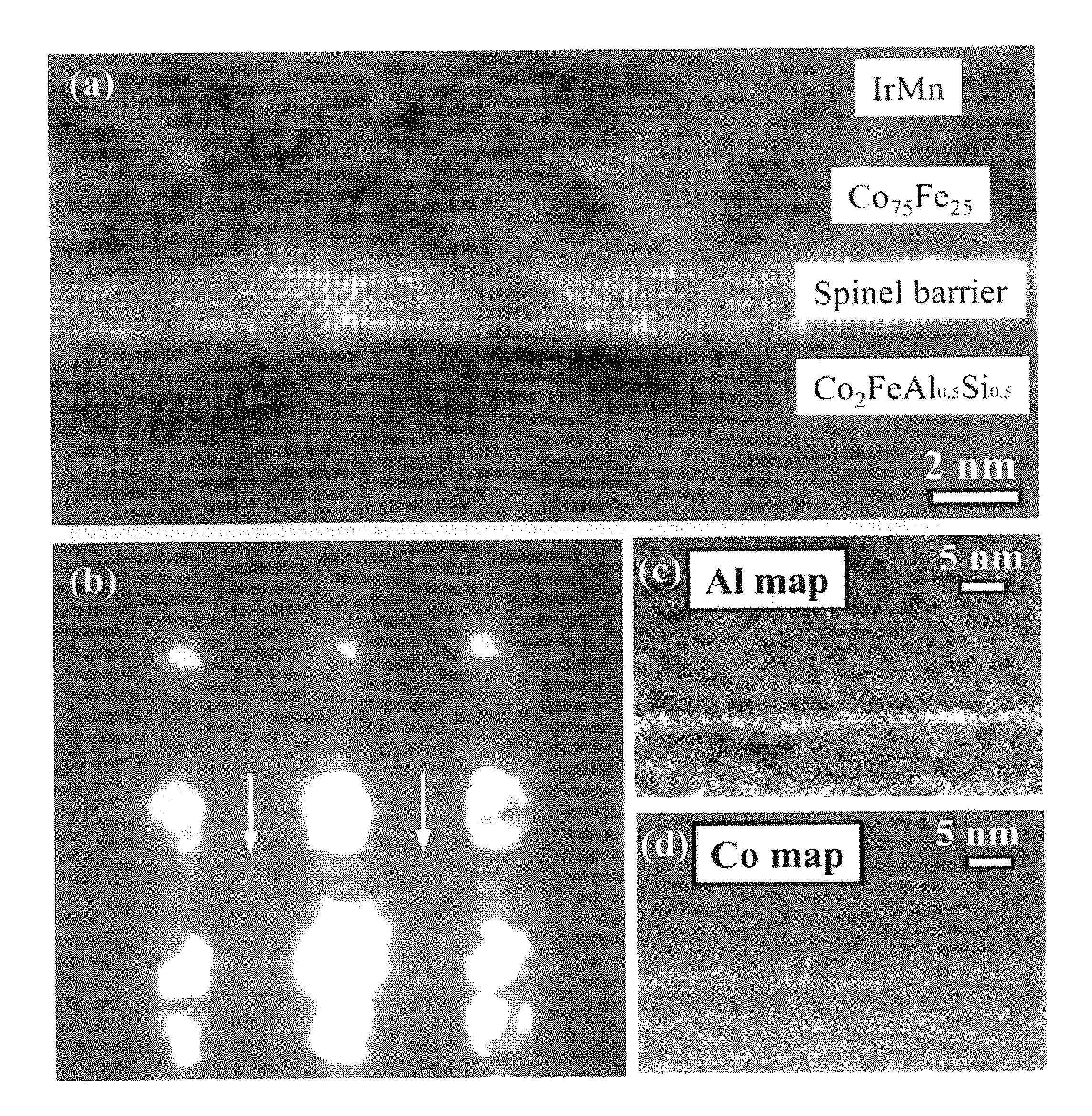
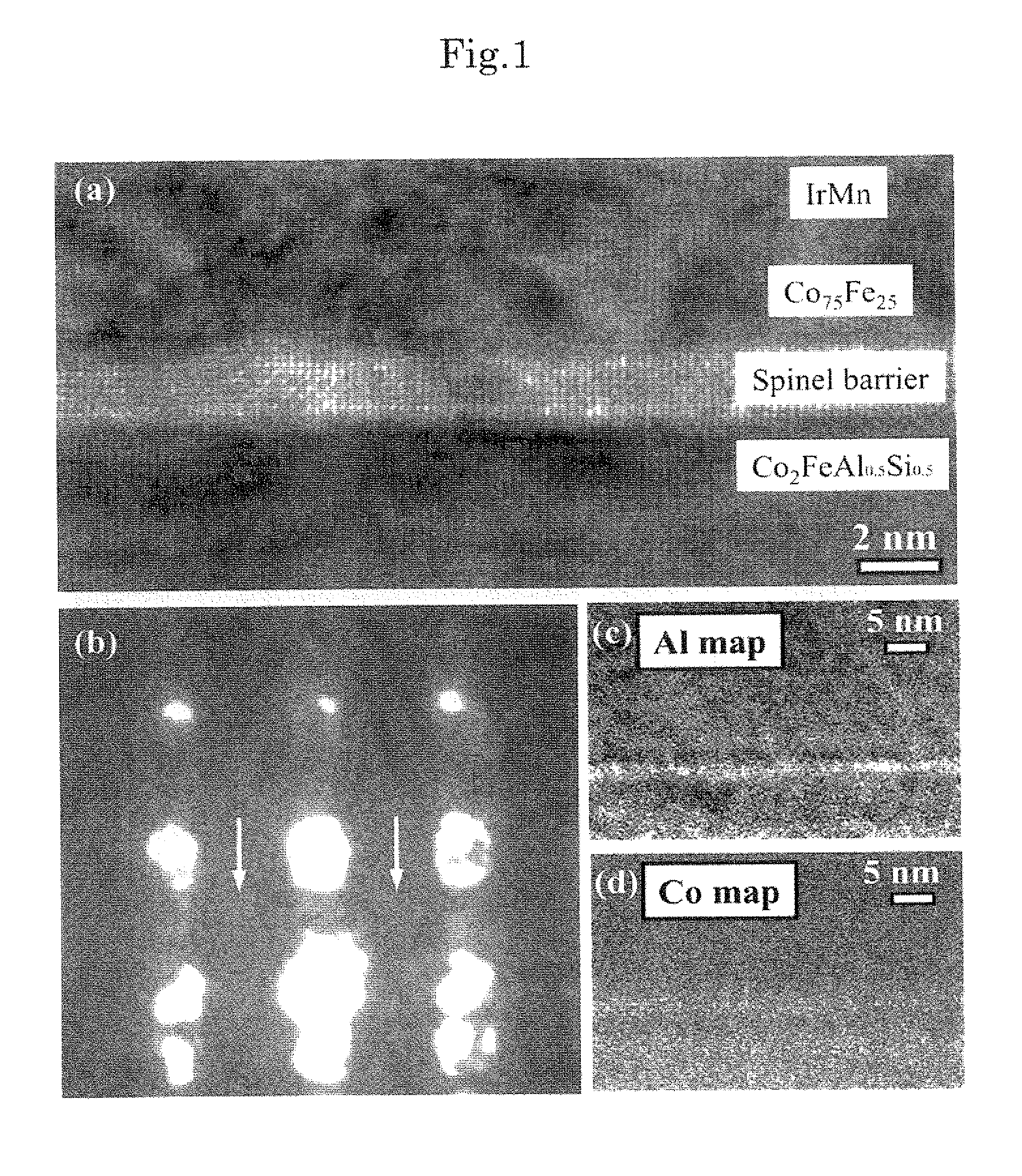
[0050]Using a DC magnetron sputtering apparatus and using a Cr film as a buffer layer, a Cr (40 nm) / Co2FeAl0.5Si0.5 (80 nm) stacked film was formed on a MgO (001) substrate. Then, for improving the Co2FeAl0.5Si0.5 (CFAS) film in crystalline properties, the stacked film was subjected to heat treatment at a temperature of 430° C. for one hour. The X-ray diffraction has revealed that the CFAS in this state is of a B2 structure. Subsequently, Mg and Al targets were sputtered to form a Mg (0.7 nm) / Al (1.3 nm) stacked film, and the resultant substrate was transferred to an oxidation chamber. Ar and oxygen were introduced into the oxidation chamber and the stacked film was subjected to inductively coupled plasma (ICP) oxidation treatment to form a Mg—Al oxide film. In this instance, the Ar:oxygen partial pressure ratio was 3:17, and the oxidation time was 120 seconds.

[0051]The resultant stacked film was transferred again to the film formation chamber, and subsequently, a CoFe (3 nm) / IrMn (...

example 2

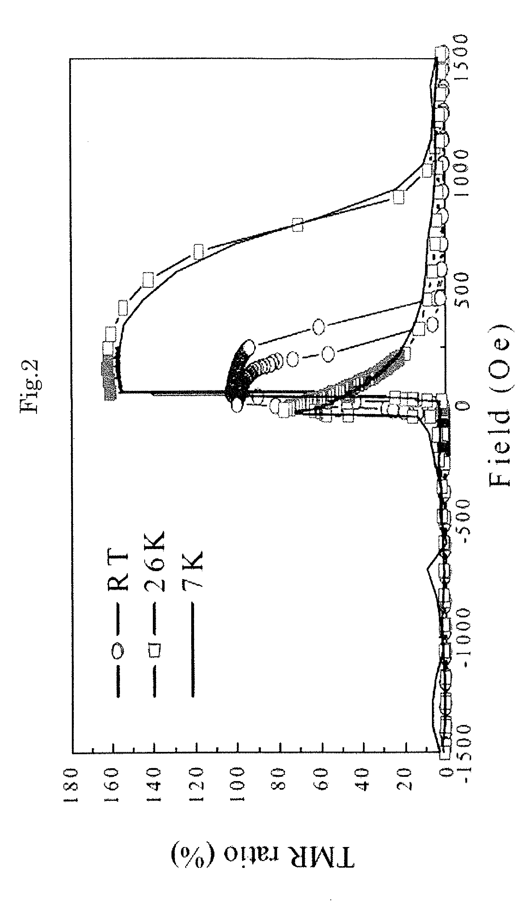
[0060]A tunnel junction element comprising Cr (40 nm) / CFAS (80 nm) / MgAl2O4 / CFAS (5 nm) / CoFe (3 nm) / IrMn (12 nm) / Ru (7 nm) was prepared using substantially the same method as in Example 1 except that the upper magnetic layer was CFAS instead of the CoFe alloy. The junction resistance RA was 2.2×10⁴ Ωμm2, which was as small as a hundredth of that obtained when using an amorphous AlOx barrier, and the TMR was 240% at room temperature, which was larger than that obtained when using a CoFe alloy in the upper magnetic layer. This indicates that CFAS having a B2 structure is grown epitaxially on the MgAl2O4 barrier and the resultant CFAS has a spin polarization larger than that of CoFe.

example 3

[0061]A tunnel junction element comprising Cr (40 nm) / CoFe (80 nm) / MgAl2O4 / CFAS (5 nm) / CoFe (3 nm) / IrMn (12 nm) / Ru (7 nm) was prepared using substantially the same method as in Example 1 except that the lower magnetic layer was a CoFe alloy. The TMR at room temperature was 68%, which was equivalent to or more than that of the element using an amorphous AlOx barrier. On the other hand, the junction resistance RA was 1.1×10⁴ Ωμm2, which was reduced to a hundredth of that of the element using an amorphous AlOx barrier. This indicates that the lattice misfit between the CoFe [110] and the MgAl2O4 [100] is as very small as 0.4% or less and a high-quality epitaxial film has been realized.


PUM

PropertyMeasurementUnit
temperatureaaaaaaaaaa
bias voltageaaaaaaaaaa

Abstract

Disclosed is a ferromagnetic tunnel junction structure which is characterized by having a tunnel barrier layer that comprises a non-magnetic material having a spinel structure. The ferromagnetic tunnel junction structure is also characterized in that the non-magnetic material is substantially MgAl2O4. The ferromagnetic tunnel junction is also characterized in that at least one of the ferromagnetic layers comprises a Co-based full Heusler alloy having an L21 or B2 structure. The ferromagnetic tunnel junction structure is also characterized in that the Co-based full Heusler alloy comprises a substance represented by the following formula: Co2FeAlxSi1-x (0≦x≦1). Also disclosed are a magnetoresistive element and a spintronics device, each of which utilizes the ferromagnetic tunnel junction structure and can achieve a high TMR value, that cannot be achieved by employing conventional tunnel barrier layers other than a MgO barrier.

Description

TECHNICAL FIELD[0001]The present invention relates to a ferromagnetic tunnel junction structure comprising a structure having a tunnel barrier layer disposed between two ferromagnetic layers and a magnetoresistive element using the same and the application to a spintronics device.BACKGROUND ART[0002]In recent years, a Giant Magnetoresistance (GMR) effect element comprising a multilayer film of a ferromagnetic layer / non-magnetic metal layer and a ferromagnetic tunnel junction (MTJ) comprising a ferromagnetic layer / insulator layer / ferromagnetic layer have attracted attention as new magnetic field sensor and non-volatile magnetic random access memory (MRAM) cell. With respect to the GMR, there have been known a CIP-GMR of a type such that an electric current flows within the plane of the film and a CPP-GMR of a type such that an electric current flows in the direction perpendicular to the plane of the film. The principle of the GMR resides mainly in spin-dependent scattering at the int...

Claims


Application Information

Patent Timeline
Patent Type & Authority Applications(United States)
IPC IPC(8): H01L29/82H01L21/02
CPCB82Y10/00B82Y25/00G11B5/3906G11B5/3909H01F10/1936B82Y40/00H01L43/08H01L43/10G01R33/098H01F41/307H01F10/3254G11C11/161H10N50/85H10N50/10
Inventor SUKEGAWA, HIROAKIINOMATA, KOICHIROSHAN, RONGKODZUKA, MASAYAHONO, KAZUHIROFURUBAYASHI, TAKAOWANG, WENHONG
Owner NAT INST FOR MATERIALS SCI
Why Eureka
Try Eureka