Methods of Optimizing Vehicular Air Conditioning Control Systems

Inactive Publication Date: 2008-02-14
GM GLOBAL TECH OPERATIONS LLC
View PDF5 Cites 76 Cited by
  • Summary
  • Abstract
  • Description
  • Claims
  • Application Information

AI Technical Summary

Benefits of technology

[0005]In view of the aforementioned considerations, the present invention optimizes air conditioning systems for vehicles by momentarily reducing A/C condenser

Problems solved by technology

Those losses typically are momentarily exacerbated when the vehicle operates on a steep gradient and/or is towing a trailer, especially when the ambient air temperature is high.
In current production vehicles having power train controls, when propulsion cooling syste

Method used


Image

  • Methods of Optimizing Vehicular Air Conditioning Control Systems
  • Methods of Optimizing Vehicular Air Conditioning Control Systems
  • Methods of Optimizing Vehicular Air Conditioning Control Systems

Examples


Embodiment Construction

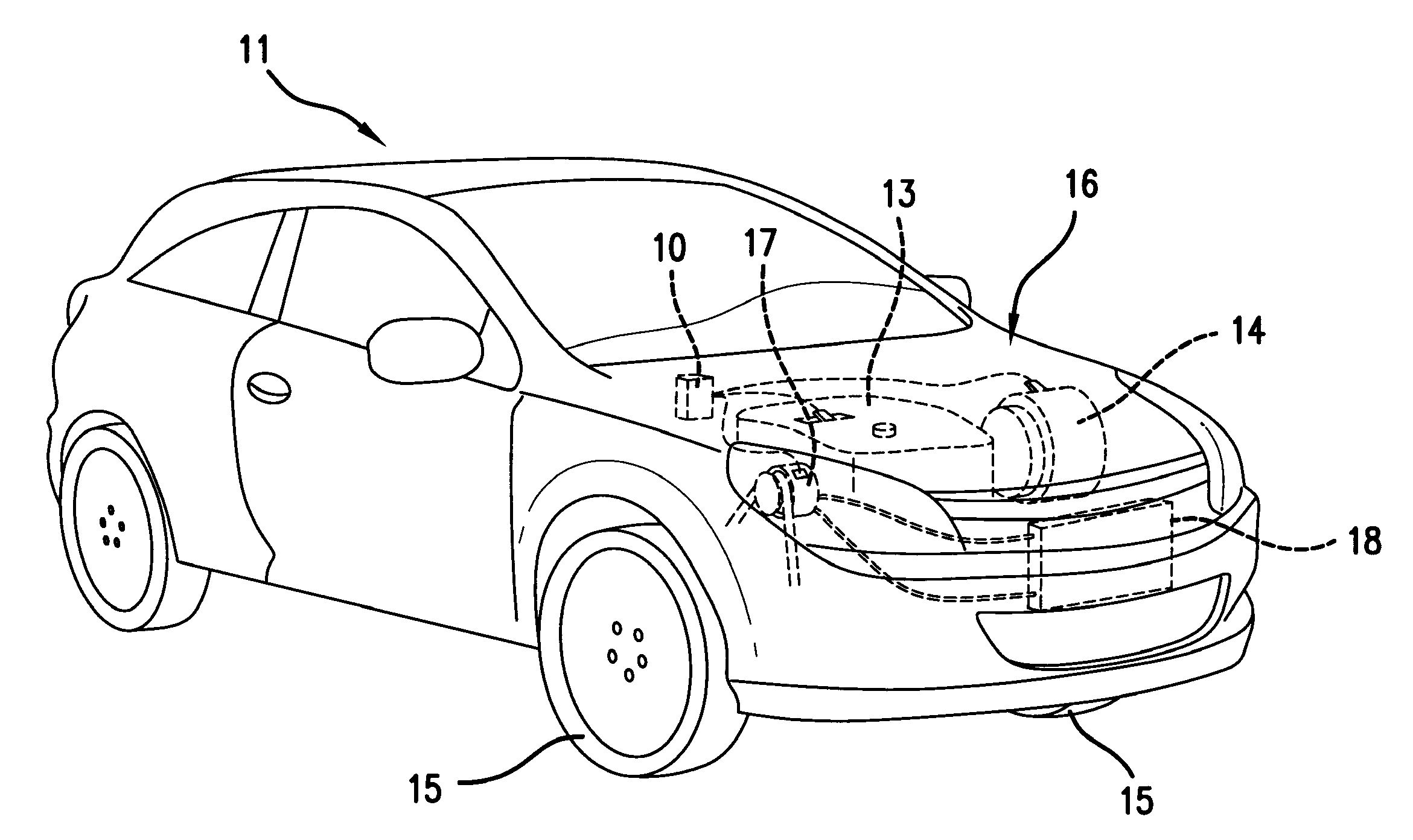
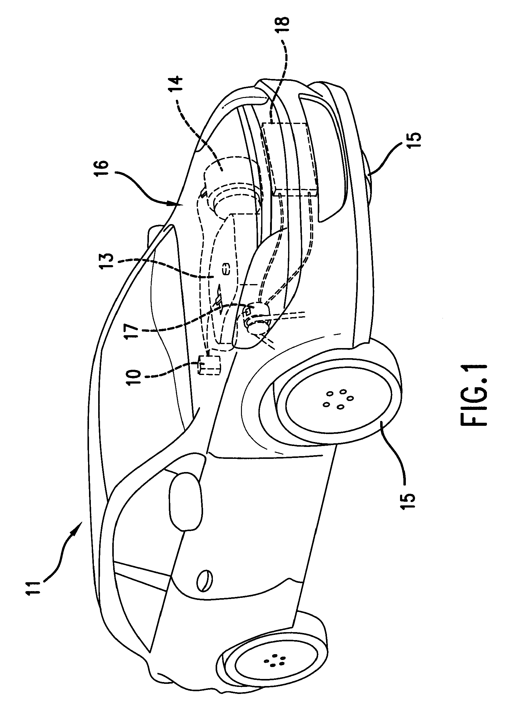
[0023]Referring now to FIG. 1, a controller 10 in a hybrid vehicle 11 selectively connects an IC engine 13 or an electric traction motor 14 to the drive wheels 15 of the hybrid vehicle. The controller 10 is mounted at any convenient location in the vehicle 11, but typically is mounted in an engine compartment 16. Controllers such as cabin temperature controllers and controllers for HVAC systems including a compressor 17 and a condenser 18 are preferably installed in the cabin, for example, within the instrument panel, or under the seats, or maybe installed in the trunk.

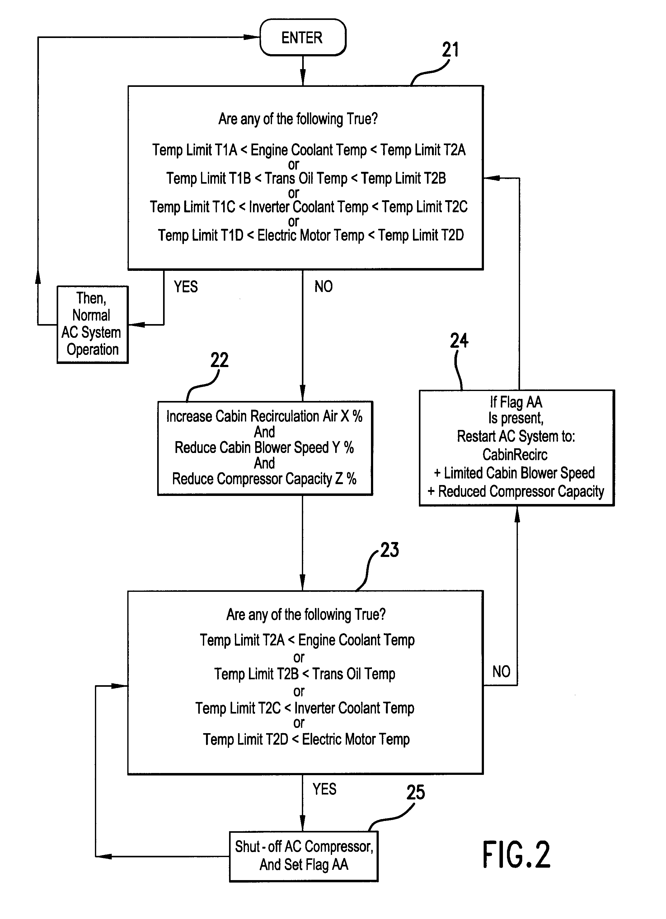
[0024]FIG. 2 is a flow chart outlining the step-by-step operation of a controller 10 according to the invention. In the “initial step,” the controller 10 checks a first truth table 21 to determine if any of the following conditions are true:[0025]1) whether the operating temperature of the engine coolant is higher than a temperature limit T1A and lower than a temperature limit T2A, or[0026]2) whether the operating tem...


PUM


Abstract

Air conditioning system controls are optimized for an air conditioning system having a compressor in IC engine vehicles and in hybrid or fuel cell vehicles having electric drive motors by first determining the operating temperature of at least one of the following vehicle components: engine coolant and transmission oil for all types of vehicles, and for hybrid or fuel cell vehicles also determining the operating temperature of inverter coolant and the electric drive motors. At least one operating temperature is then compared to lower and upper temperature limits. If the operating temperature is outside of the temperature limits air conditioner heat load is reduced by at least one of the following steps: increasing cabin air recirculation, reducing cabin blower speed and reducing air conditioner compressor capacity. Subsequent to reducing air conditioner heat load, selected operating temperature or temperatures are monitored to determine if the operating temperature exceeds the upper temperature limit or limits. If the operating temperature or temperatures exceed the upper limit or limits the compressor is shut off.

Description

FIELD OF THE INVENTION[0001]The present invention is directed to methods of optimizing vehicular air conditioning control systems. More particularly, the present invention is directed to such methods which result in reduced propulsion cooling system size in non-hybrid vehicles and lower operating temperature for coolant loops in hybrid and fuel cell vehicles.BACKGROUND OF THE INVENTION[0002]Conventional vehicle propulsion cooling systems include heat exchangers and fans, the size of which is based on propulsion system losses. Losses are absorbed by engine coolant, engine oil and transmission oil. Those losses typically are momentarily exacerbated when the vehicle operates on a steep gradient and / or is towing a trailer, especially when the ambient air temperature is high. With respect to hybrid and fuel cell vehicles, propulsion cooling loops require lower operating temperatures than conventional power train vehicles.[0003]Air conditioning condensers are typically the first heat exch...

Claims


Application Information

Patent Timeline
IPC IPC(8): F25D17/00F25B49/00
CPCB60H1/00385B60H1/00735B60H1/00764B60H1/00828B60H2001/3282B60H1/00878B60H1/3208B60H2001/3266B60H2001/327B60H1/00849B60H1/00B60H1/32
Inventor ZIEHR, LAWRENCE P.DONIS, PETER A.MAJOR, GREGORY A.NEMESH, MARK D.
Owner GM GLOBAL TECH OPERATIONS LLC
Why Eureka
Try Eureka