Fuel filter system

a filter system and fuel technology, applied in the direction of filtration separation, multi-stage water/sewage treatment, separation process, etc., can solve the problems of reducing affecting the efficiency of water separation, and the filter system as a whole losing water separation properties, etc., to achieve the effect of simple structur

Inactive Publication Date: 2008-02-14
MANN HUMMEL GMBH
View PDF11 Cites 28 Cited by
  • Summary
  • Abstract
  • Description
  • Claims
  • Application Information

AI Technical Summary

Benefits of technology

[0008] An advantage of the invention is that the coalescer element has a simple structure, and particularly the seal plate or end plate necessary for sealing is formed as a single piece and extends to a wall of the housing. This eliminates the need for an additional sealing element.
[0009] In a further refinement of the invention, the seal plate or end plate is formed of a two-component synthetic resin material, such that the first component is a conventional thermoplastic synthetic resin material and the second component an elastomer. The second component carries out the sealing function along the wall of the housing. In place of a two-component seal plate, it is also possible to use a seal ring or a molded seal. This seal ring or molded seal is arranged in the radially outer region of the end plate and is in any case located outside the effective coalescer area.
[0010] In another embodiment of the invention the fluid inlet opening provided on the housing and the fluid inlet opening on the end plate of the coalescer are substantially registered or aligned so that the fluid does not change direction as it flows into the coalescer. This has the advantage that if water droplets have already formed in the fuel, they will no...

Problems solved by technology

A disadvantage of this construction is that the primary filter element becomes loaded with dirt because of its filtering properties, and this dirt reduces or prevents flow through the filter.
Furthermore, the primary filter ...

Method used


Image

  • Fuel filter system
  • Fuel filter system
  • Fuel filter system

Examples


Embodiment Construction

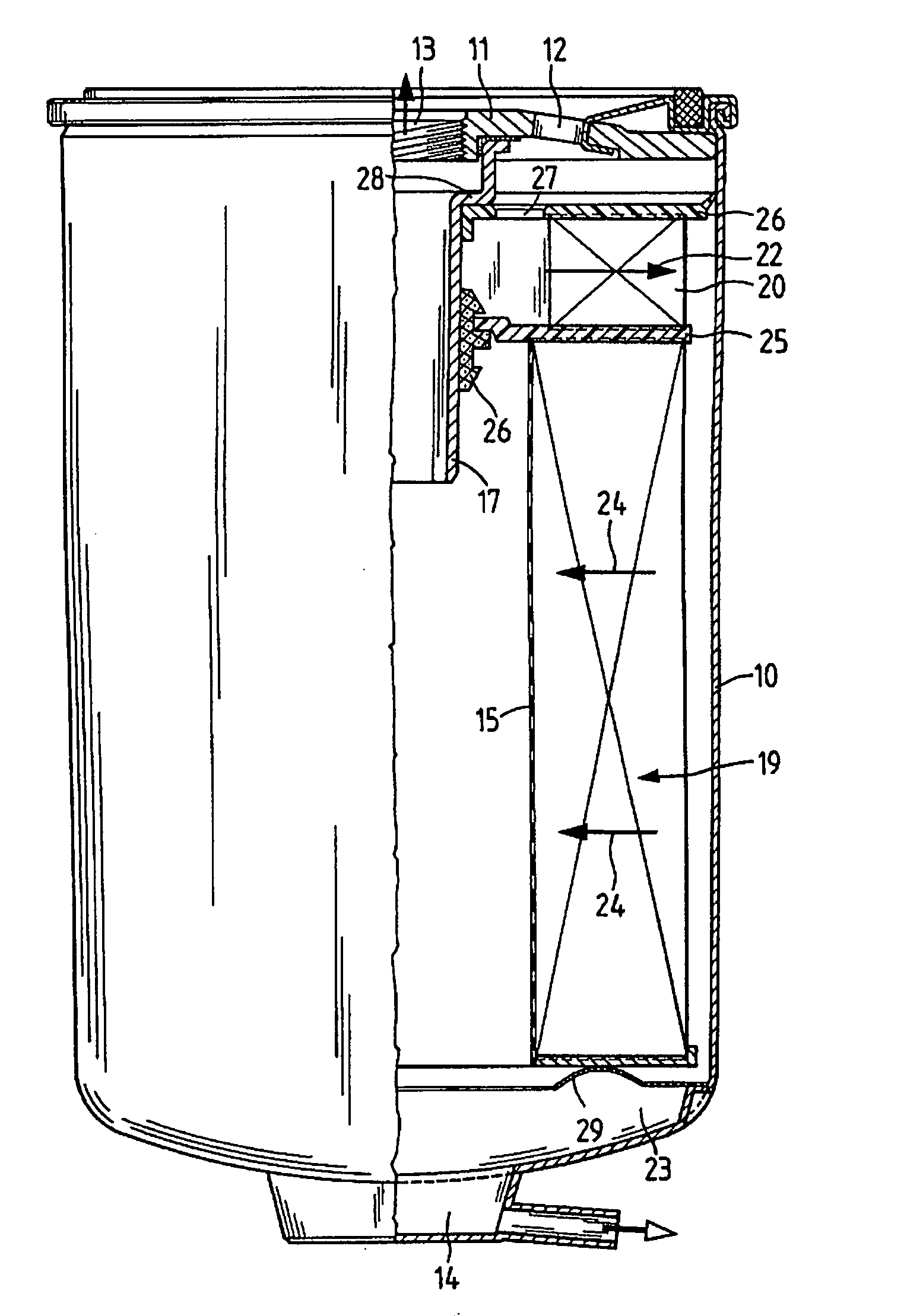
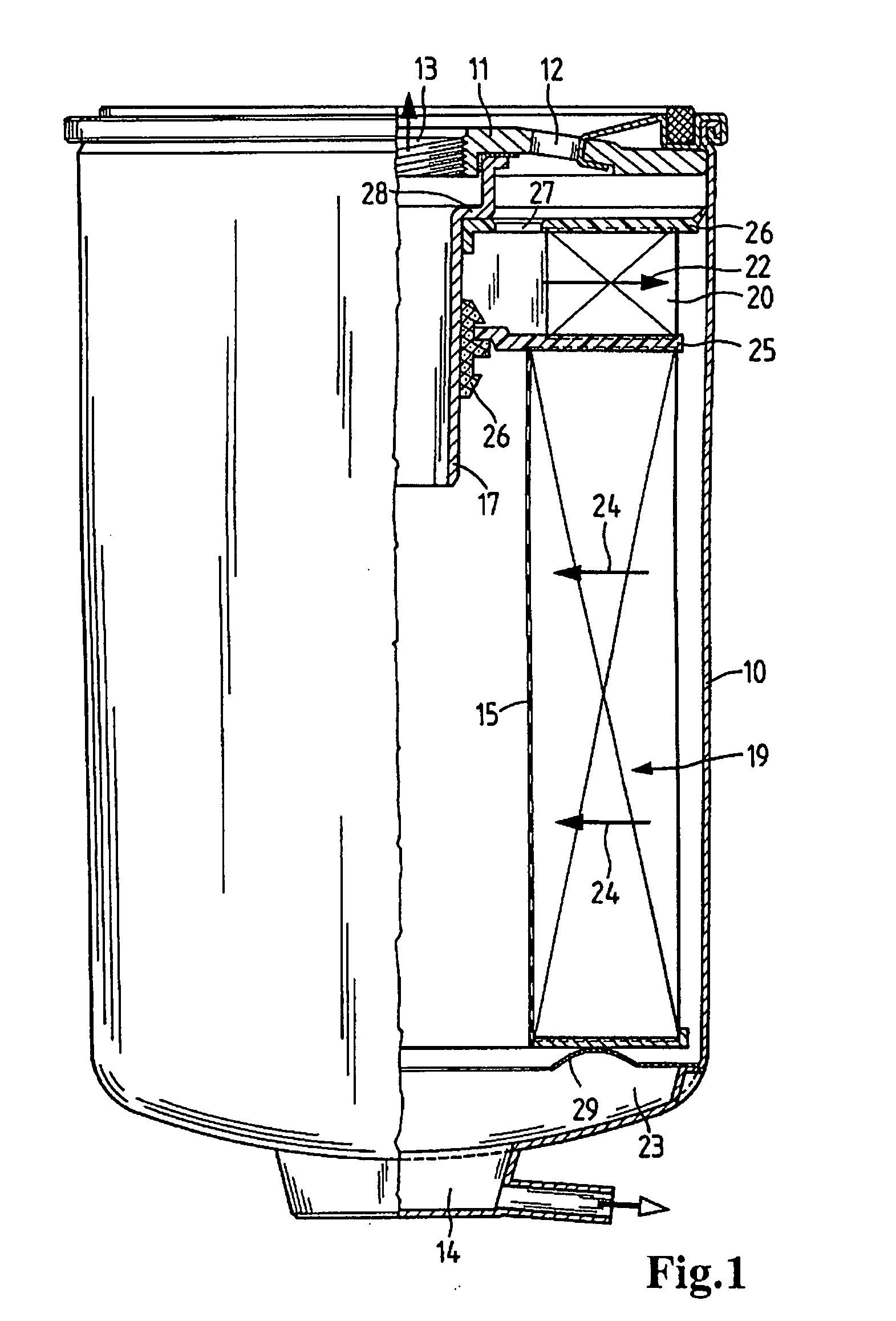
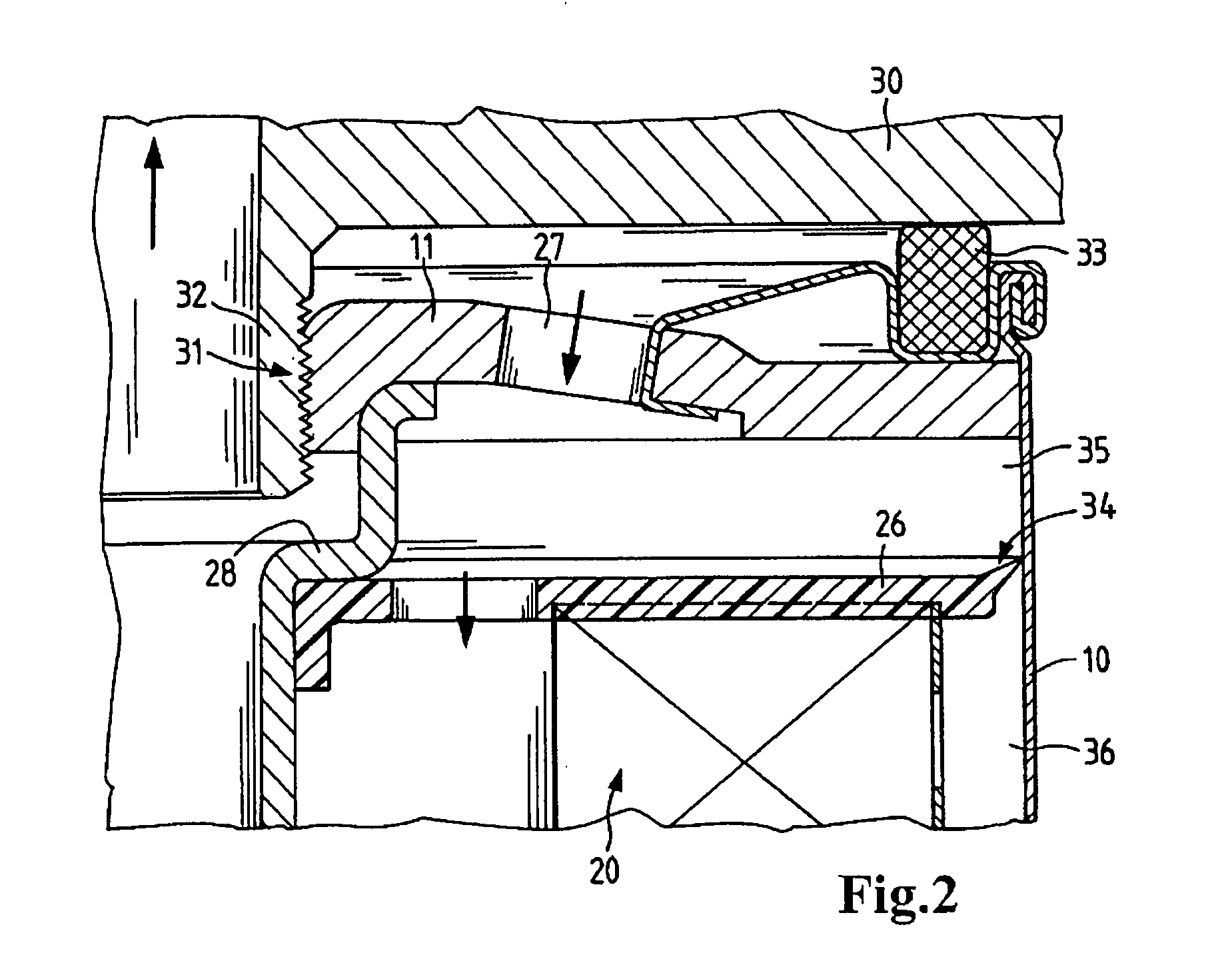
[0020] A fuel filter according to the invention as shown in FIG. 1 has a housing 10 which is a substantially cylindrical vessel. The top of housing 10 is closed by a cover 11. Cover 11 has inlet openings 12 for the fuel to flow in. One of these openings is shown in the figure. These inlet openings are configured as bores and are uniformly distributed around a partial circle. Furthermore, an outlet opening 13 is provided, from which the filtered fuel can be discharged. At the lower end of the housing 10 is a water discharge valve 14, which is indicated only schematically in the figure. A discharge tube 17 is located within the housing.

[0021] Inside the housing 10 is a particle filter 19 that is formed of a pleated filter material which may be constructed of a plurality of layers. A coalescer element 20 is arranged upstream of the particle filter 19. In the illustrated embodiment, this coalescer element is also formed of a pleated medium. This medium can be a polyester material, a po...


PUM

PropertyMeasurementUnit
Transparencyaaaaaaaaaa
Hydrophobicityaaaaaaaaaa

Abstract

A fuel filter system characterized by a simple design provided with a coalescer element (20) disposed in the immediate fuel inlet region for improving the elimination of water droplets. The coalescer element includes an upper end plate (26) that extends to the inner wall of the housing (10), thereby sealing the coalescer element as well as the inlet region and the outer unfiltered fluid region. The coalescer element (20) and the particle filter (19) are arranged on a common separating element (25), which rests against the discharge tube (17) located in the center of the fuel filter via a profiled seal. The end plate of the coalescer element can be produced with the profiled elastomeric seal molded thereon by two-component injection molding or by overmolding.

Description

CROSS REFERENCE TO RELATED APPLICATIONS [0001] This application is a continuation of international patent application no. PCT / EP2006 / 050647, filed Feb. 3, 2006 designating the United States of America, and published in German on Aug. 17, 2006 as WO 2006 / 084823, the entire disclosure of which is incorporated herein by reference. Priority is claimed based on Federal Republic of Germany patent application no. DE 10 2005 005 848.5, filed Feb. 8, 2005.BACKGROUND OF THE INVENTION [0002] The present invention relates to a fuel filter system suitable for a liquid fuel such as diesel fuel, in which a particle filter is provided inside a housing. [0003] U.S. Pat. No. 5,084,170 discloses a fuel filter which has a housing enclosing a primary filter element and a secondary filter element. Fuel flows through the primary filter element from the inside to the outside. The primary filter element also has coalescing properties, so that any water that may be present in the fuel coalesces, i.e., larger...

Claims


Application Information

Patent Timeline
IPC IPC(8): B01D35/02B01D35/16B01D35/18B01D36/00
CPCB01D36/003B01D27/148F02M37/24
Inventor KLEIN, GUNNAR-MARCELJOKSCHAS, GUENTERKLEIN, MARTIN
Owner MANN HUMMEL GMBH
Why Eureka
Try Eureka