Brake hydraulic pressure control unit for vehicle

a technology for controlling units and brakes, which is applied in the direction of brake types, brake components, brake systems, etc., can solve the problems of increasing the lateral width (horizontal dimension) of the hydraulic block, the control unit cannot be mounted on the vehicle, and the mounting difficulty of the control unit on the vehicle, so as to reduce the width of the brake and be mounted more easily

a technology for controlling units and brakes, which is applied in the direction of brake types, brake components, brake systems, etc., can solve the problems of increasing the lateral width (horizontal dimension) of the hydraulic block, the control unit cannot be mounted on the vehicle, and the mounting difficulty of the control unit on the vehicle, so as to reduce the width of the brake and be mounted more easily

US20080036295A1Inactive Publication Date: 2008-02-14ADVICS CO LTD

Image

  • Brake hydraulic pressure control unit for vehicle
  • Brake hydraulic pressure control unit for vehicle
  • Brake hydraulic pressure control unit for vehicle

Examples


Embodiment Construction

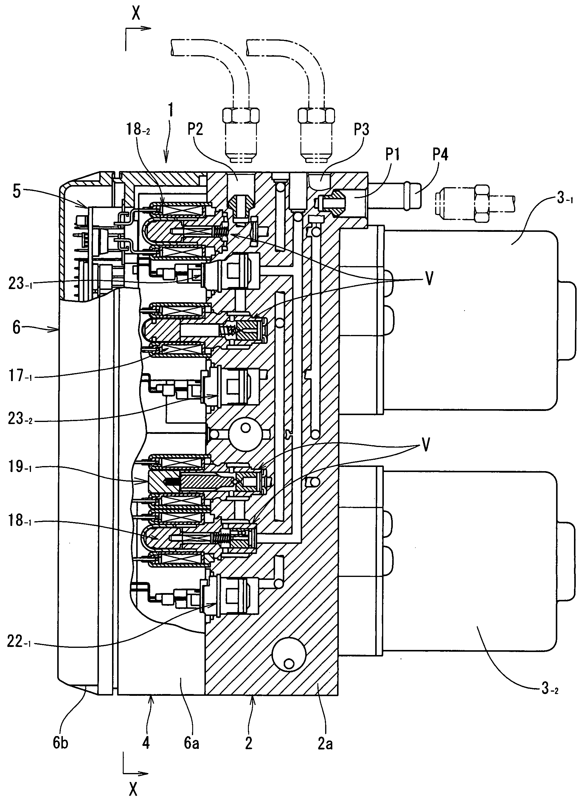
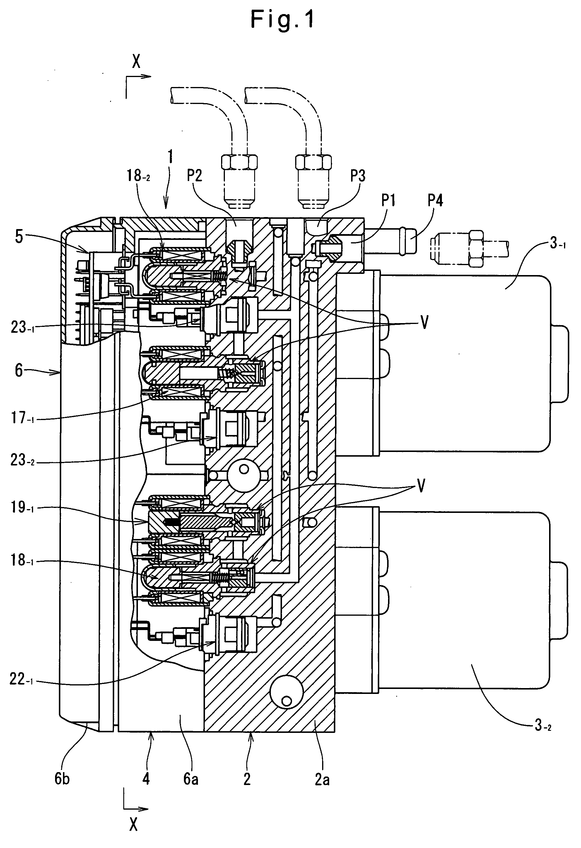
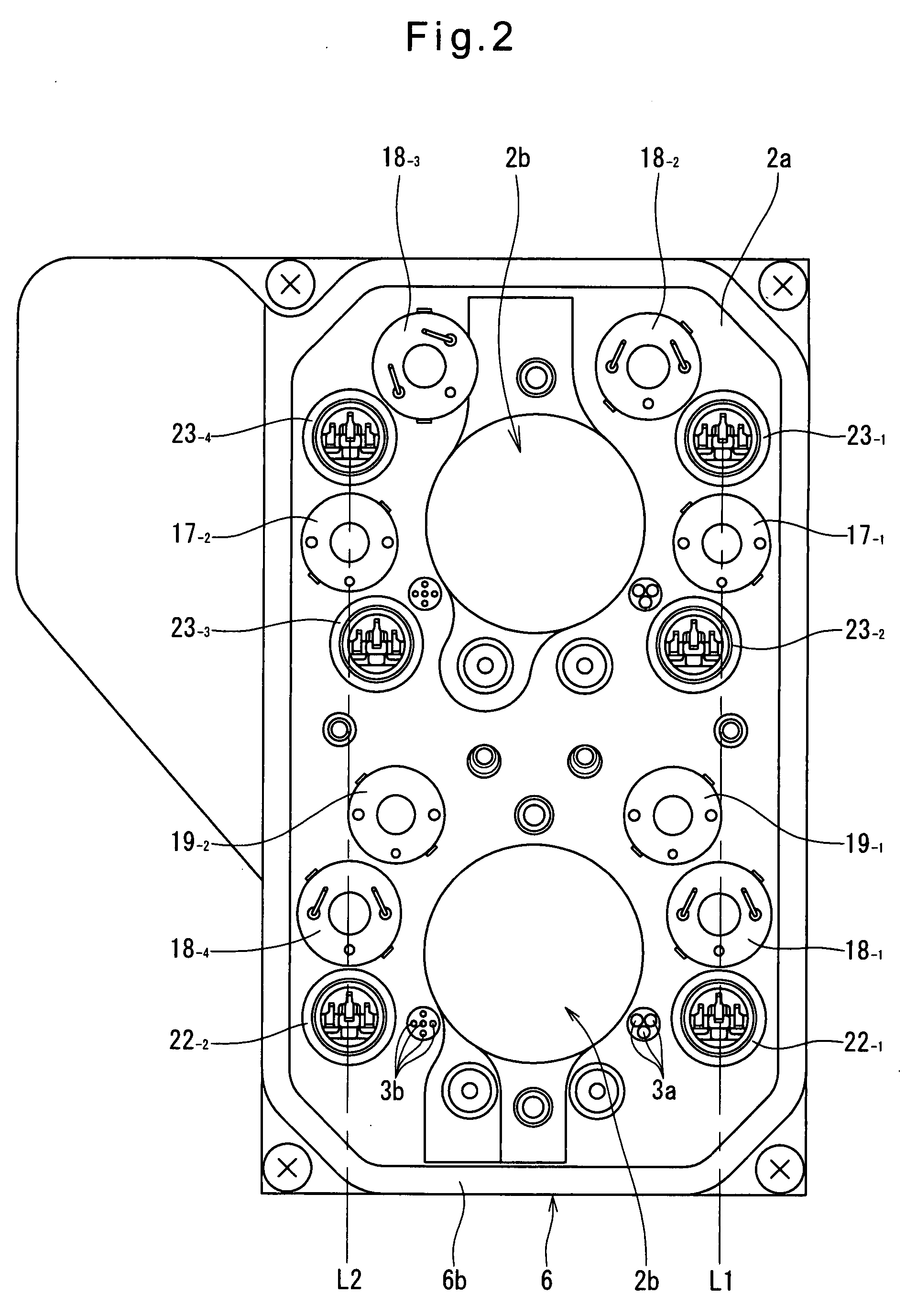
[0023]Now the embodiment of the present invention is described with reference to FIGS. 1 to 4. In the description and the drawings, any plurality of identical elements are individually denoted by identical main numbers with different sub-numbers (-1, -2, -3 . . . ) attached thereto. FIGS. 1 to 3 show a brake hydraulic pressure control unit 1 embodying the present invention, which comprises a hydraulic block 2, motors 3-1 and 3-2, and an electronic control unit 4.

[0024]FIG. 4 shows a circuit configuration of a brake system of the brake-by-wire type which includes four pumps each provided for one of the four wheels of the vehicle, and two motors each for individually driving two of the four pumps. The brake hydraulic pressure control unit of FIGS. 1 to 3 is used in the brake system of FIG. 4. The brake system of FIG. 4 is first described.

[0025]The brake system of FIG. 4 includes a brake operating member (typically a brake pedal as shown), a stepping force sensor 12 for detecting the d...


PUM


Abstract

A brake hydraulic pressure control unit includes motors mounted on one end of a hydraulic block so as to be aligned along a vertical direction. Each motor drives one of two sets of pumps. Solenoid valves and an electronic control unit are provided at the other end of the hydraulic block. Half of the solenoid valves and other component parts, which form a first hydraulic circuit, are provided in a vertically elongated area on the left-hand side of the pump mounting portions, and the other half of the solenoid valves and other component parts, which form a second hydraulic circuit, are provided in a vertically elongated area on the right-hand side of the pump mounting portions, with the component parts of each of the first and second hydraulic circuits overlapping each other in the lateral direction.

Description

CROSS REFERENCE TO RELATED APPLICATIONS[0001]This application is based on and claims priority under 35 U.S.C. sctn. 119 with respect to Japanese Patent Application No. 2006-220321 filed on Aug. 11, 2006, the entire content of which is incorporated herein by reference.BACKGROUND OF THE INVENTION[0002]The present invention relates to a brake hydraulic pressure control unit for a vehicle for controlling hydraulic pressures in the wheel cylinders mounted to the respective wheels of the vehicle based on commands from an electronic control unit.[0003]Such brake hydraulic pressure control units, which are used in vehicle hydraulic brake systems having such functions as anti-lock brake control (ABS) and electronic stability control (ESC) functions, comprise a hydraulic block including a housing, and pumps and solenoid valves mounted to the housing, a motor for driving the pumps, and an electronic control unit including a motor driving circuit and solenoid valve control circuits. The solenoi...

Claims


Application Information

Patent Timeline
14 Feb 2008
Publication
US20080036295A1
IPC
B60T8/40
CPC
B60T8/368; B60T13/18; B60T8/4081; Y10S303/10
Inventors
SAKAI, MORIHARU