Method and system for measurement of current flows in fastener arrays

a technology of fastener array and current flow, which is applied in the direction of magnetic measurement, instruments, base element modification, etc., can solve the problems of sparks, affecting the accuracy of current flow measurement, and reducing the capacity of carrying current,

Active Publication Date: 2008-02-14
THE BOEING CO
View PDF5 Cites 32 Cited by
  • Summary
  • Abstract
  • Description
  • Claims
  • Application Information

AI Technical Summary

Problems solved by technology

Using composite materials for fuel filled (a.k.a., wet) composite primary structures poses a significant lightning strike concern as composite structures have a diminished capacity for carrying current as compared to aluminum and are far more susceptible to damage from lightning strike attachments.
When lightning strikes a composite structure on an aircraft, it can cause a spark to occur by attaching to the composite structure such that a high amount of current traverses between various materials in the composite structure and jumps between the dielectric gaps between the various materials.
The risk from uncontrolled transport of current is that certain geometries are prone to developing sparks above geometry-specific threshold levels (threshold is defined as the lowest value of the peak current of a transient lightning pulse at which arcing or sparking is seen to occur).
Directly measuring the current in fasteners has been difficult due to space limitations within a densely-fastened joint.
Conventional methods for current flow measurement, such as Rogowski Coils, have been impracticable to use because of the space limitations.
However, a problem exists in that it is extremely difficult to measure current flow through individual components in a multi-component structural composite joint.

Method used


Image

  • Method and system for measurement of current flows in fastener arrays
  • Method and system for measurement of current flows in fastener arrays
  • Method and system for measurement of current flows in fastener arrays

Examples


Embodiment Construction

[0025]The following detailed description is of the best currently contemplated modes of carrying out the invention. The description is not to be taken in a limiting sense, but is made merely for the purpose of illustrating the general principles of the invention, since the scope of the invention is best defined by the appended claims.

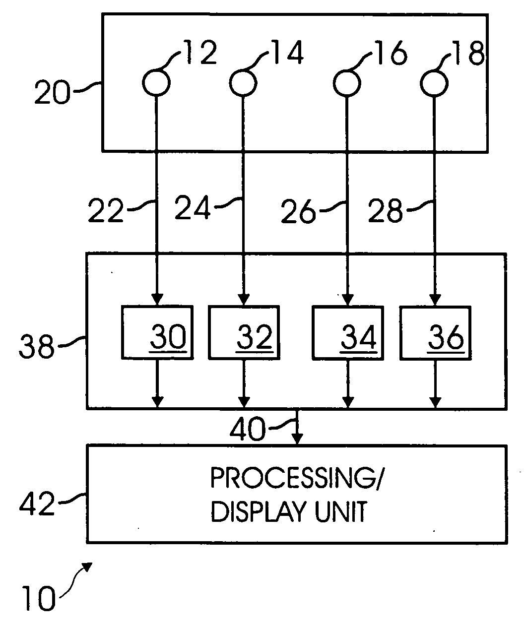
[0026]According to the present invention, a method and system for measuring current flows through individual components in a multi-component composite structure, such as individual fasteners in a multi-fastener structural composite joint, is provided. Although the method and system of the present invention is implemented using an aircraft, those skilled in the art will recognize that the principles and teachings described herein may be applied to a variety of structures with composite surfaces, such as automobiles, ships, helicopters, and trains.

[0027]Potential modifications to composite structures on aircraft are continuously being developed to provide...


PUM


Abstract

A method and apparatus for simultaneously measuring current flows through individual structures in a multi-structure composite joint is provided. The method comprising inserting a printed circuit board, etched with Rogowski coil sensory circuits, inside the joint between at least two structures with the at least two structures extending through the Rogowski coil sensory circuits in the printed circuit board; detecting induced current in the at least two fasteners; transmitting the induced current to a passive integrator array for capturing transient pulses from the printed circuit board and integrating the pulses into an array output; transmitting the array output to a processing unit.

Description

CROSS REFERENCE TO RELATED APPLICATIONS[0001]NoneBACKGROUND[0002]1. Field of Invention[0003]This invention relates generally to measuring current flows, and more particularly, measuring the current flows in a mechanically fastened composite structural joint.[0004]2. Background of the Invention[0005]Traditionally aircraft have been built using aluminum as the primary airframe structural material as aluminum is an excellent electrical and thermal conductor and provides inherent lightning protection. However, structures (may also be referred to as “parts” or “components”) for aircraft are increasingly being made of carbon fiber composite materials as composites have higher specific strength and stiffness. Using composite materials for fuel filled (a.k.a., wet) composite primary structures poses a significant lightning strike concern as composite structures have a diminished capacity for carrying current as compared to aluminum and are far more susceptible to damage from lightning strik...

Claims


Application Information

Patent Timeline
Patent Type & Authority Applications(United States)
IPC IPC(8): G01R15/20
CPCG01R31/008G01R15/181
Inventor KOVACH, DANIEL J.ROBB, ANDREW M.
Owner THE BOEING CO
Why Eureka
Try Eureka