Frequency modulation apparatus and frequency modulation method

a frequency modulation apparatus and frequency modulation technology, applied in electrical apparatus, printing, pictoral communication, etc., can solve the problems of radiation noise generation, image distortion, radiation noise level, etc., and achieve the effect of reducing the radiation noise peak level

Inactive Publication Date: 2008-02-14
CANON KK
View PDF4 Cites 2 Cited by
  • Summary
  • Abstract
  • Description
  • Claims
  • Application Information

AI Technical Summary

Benefits of technology

[0010] An object of the present invention is to provide a frequency modulation apparatus capable of reducing a peak level of the radiation noise in a characteristic frequency band due to an image clock.

Problems solved by technology

The reason why is because, if the frequency of this image clock is not constant, the on / off timing of the laser light deviates from a normal timing, and thereby a dot forming position of an electrostatic latent image formed on the photosensitive body is subtly displaced, and this results in the occurrence of an image distortion, a color drift and a color shading.
However, when the image clock is always constant, there are often the cases where a radiation noise is generated and the level of the radiation noise exceeds the value defined in the international radiation noise standard in the transmission path in which the on / off signal for turning on / off the laser light is transmitted from the generating circuit to a laser light driving circuit.
Further, when the frequency modulation technology is employed, though the radiation noise level is reduced, in the case where the f-θ lens having a characteristic to such an extent that there is no need for performing the frequency modulation is used, the image clock frequency becomes constant, and therefore, the radiation noise level becomes much severe.

Method used


Image

  • Frequency modulation apparatus and frequency modulation method
  • Frequency modulation apparatus and frequency modulation method
  • Frequency modulation apparatus and frequency modulation method

Examples


Embodiment Construction

[0031] The present invention will now be described in detail below with reference to the accompanying drawings showing a preferred embodiment thereof. In the drawings, elements and parts which are identical throughout the views are designated by identical reference numeral, and duplicate description thereof is omitted.

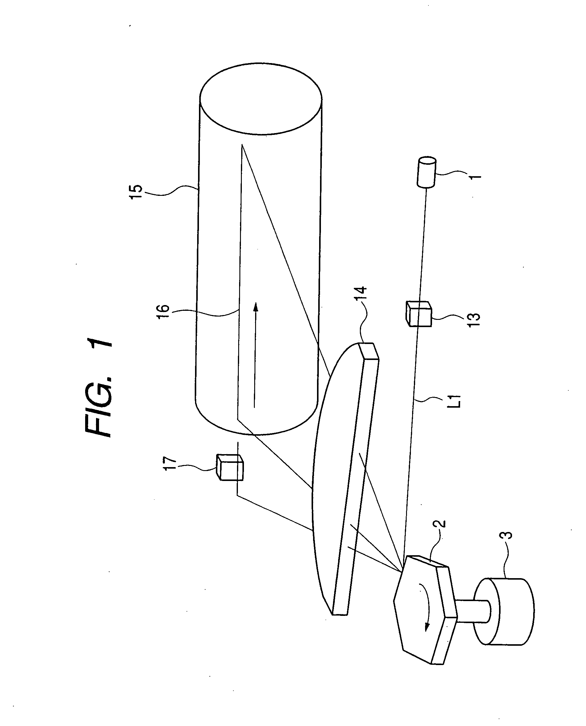
[0032] The embodiment of the present invention will be described below with reference to the drawings. FIG. 1 is a drawing schematically showing the configuration of an exposure unit of an image formatting apparatus according to one embodiment of the present invention.

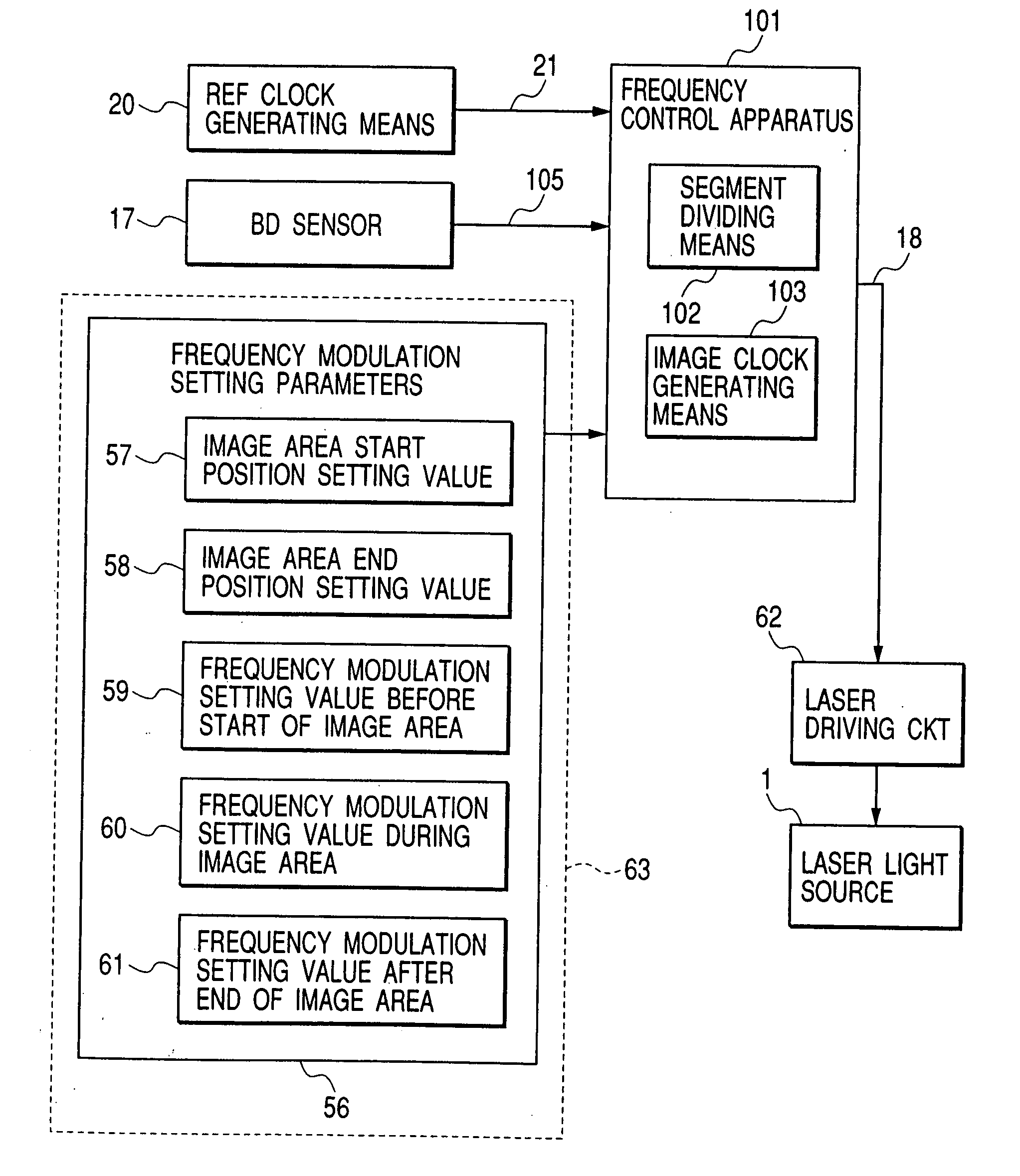
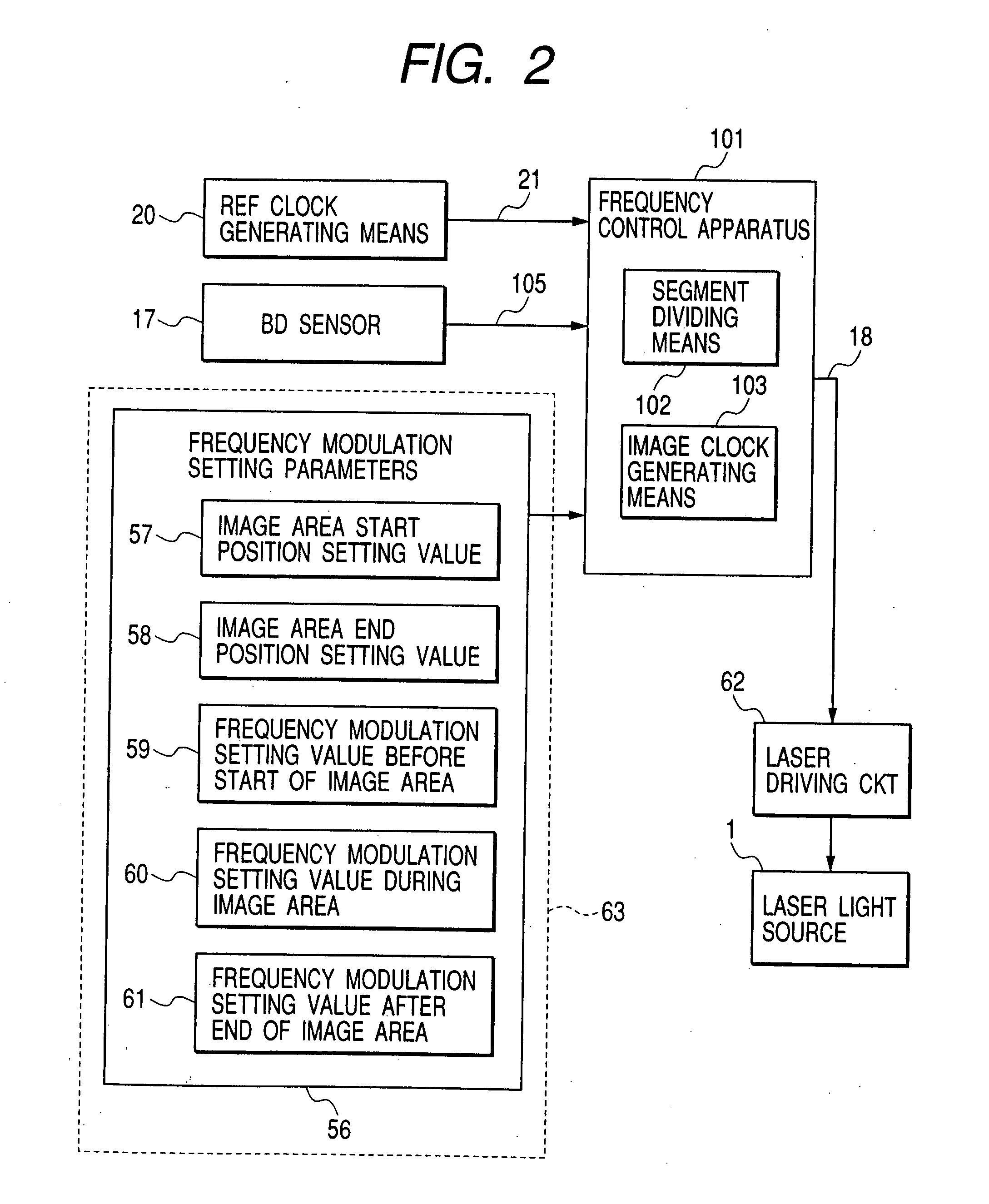
[0033] An image forming apparatus of an electrophotographic system, as shown in FIG. 1, comprises an exposure unit which irradiates laser light on a photosensitive drum 15 so that a latent image corresponding to an inputted image data is formed on the photosensitive drum 15. This exposure unit comprises a laser light source 1 emitting diffuse laser light. The laser light emitted from the laser light sou...


PUM


Abstract

A frequency modulation apparatus capable of reducing a peak level of a radiation noise of a characteristic frequency band due to an image clock. This frequency modulation apparatus is used in an image formation apparatus having an image bearing body to be scanned by a laser beam, and comprises an auxiliary clock calculating portion for calculating an auxiliary clock period based on a reference clock period and a modulation coefficient, and an image clock generating portion for generating the image clock in which a frequency is different at least in one portion and other portions of an image area on a main scan line to be scanned by the laser beam on said image bearing body based on the initial period value set in advance and said auxiliary clock period, and said image clock generating means perform a frequency modulation so that the frequency of said image clock changes within a predetermined fluctuation.

Description

BACKGROUND OF THE INVENTION [0001] 1. Field of the Invention [0002] The present invention relates to a frequency modulation apparatus and a frequency modulation method, which generate an image clock used for an on / off control of a laser beam scanning on a image bearing body such as a photosensitive drum and the like. [0003] 2. Related Background Art [0004] In general, in an image forming apparatus of an electro-photographic system, while laser light emitted from a semiconductor laser is turned on and off, this laser light is scanned by a polygonal rotating mirror (polygon mirror) so as to irradiate a photosensitive body, thereby performing a latent image formation. [0005] In such an image forming apparatus, an image clock of a constant frequency is used for an on / off control of the laser light. The reason why is because, if the frequency of this image clock is not constant, the on / off timing of the laser light deviates from a normal timing, and thereby a dot forming position of an e...

Claims


Application Information

Patent Timeline
Patent Type & Authority Applications(United States)
IPC IPC(8): B41J2/435H04N1/053H04N1/113H04N1/12
CPCH04N1/053H04N1/1135H04N1/12H04N2201/0471H04N2201/04774H04N2201/04732H04N2201/04744H04N2201/04793H04N2201/02439H04N2201/04794
Inventor SHIRAISHI, MITSUO
Owner CANON KK
Why Eureka
Try Eureka