
Switching power supply circuit

Inactive Publication Date: 2006-07-27
SONY CORP
View PDF20 Cites 14 Cited by
  • Summary
  • Abstract
  • Description
  • Claims
  • Application Information

AI Technical Summary

Benefits of technology

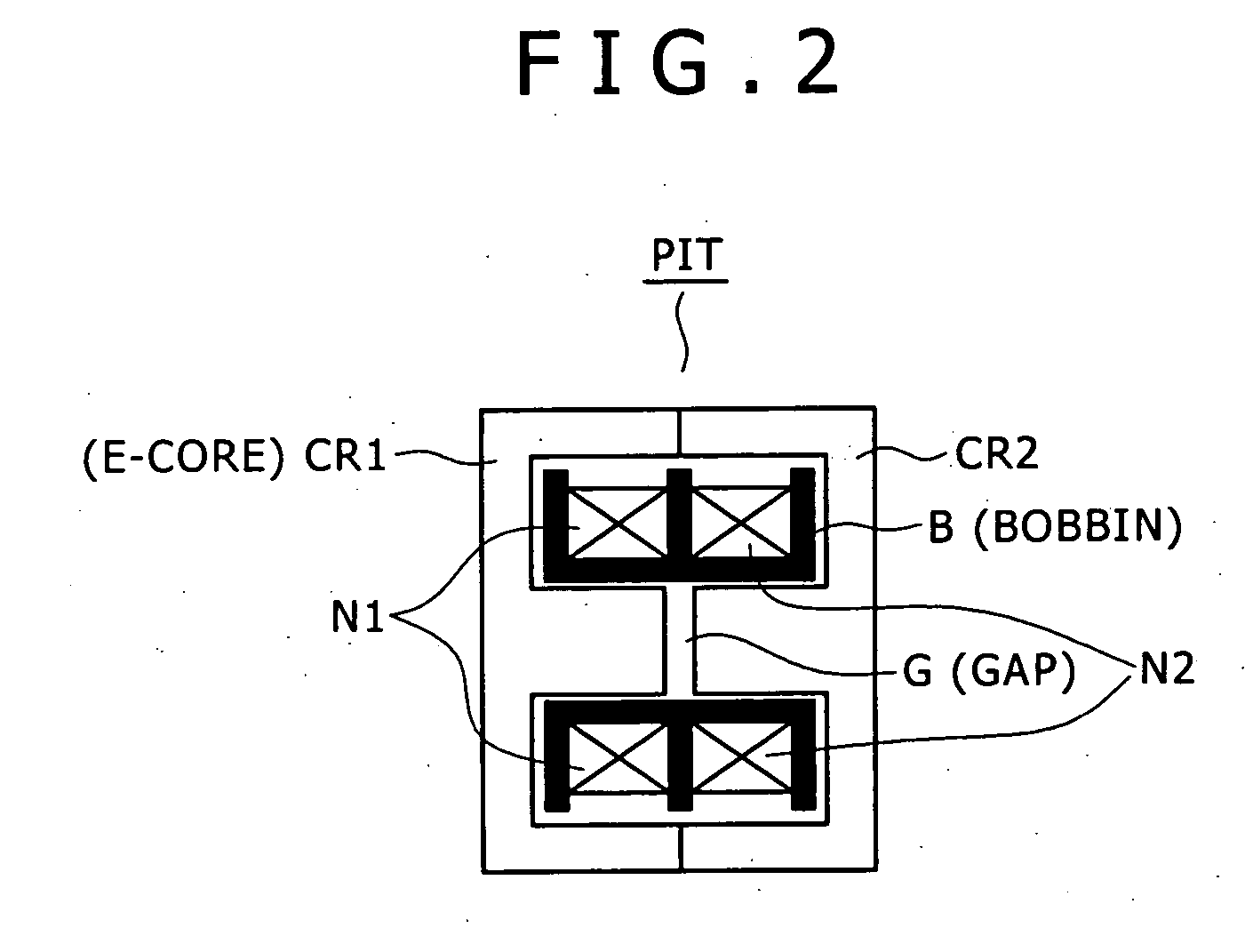
[0093] According to this configuration, a switching converter is employed for which a primary-side series resonant circuit is provided to offer current resonant operation as the switching operation of the primary side. In addition, a series resonant circuit is provided on the secondary side. Due to this configuration, the switching power supply circuit of this aspect of the invention includes a coupled resonant circuit employing electromagnetic coupling by the isolation converter transformer. On that basis, the gap length of a gap formed in a predetermined position in the core of the isolation converter transformer is set so that a coupling coefficient is obtained in which a sharp unimodal characteristic is achieved as an output characteristic with respect to a frequency signal (switching output) of the switching frequency, which is an input to the coupled resonant circuit. As a result, the switching frequency variable range (requisite control range) required for constant-voltage control can be narrowed compared with a circuit including a series resonant circuit only on the primary side.
[0094] In addition, since the first and second resonant frequencies are designed as described above, the peak level of the primary-side series resonant current when a large AC input voltage (the AC 200 V-system) is employed can be reduced, which enhances the power conversion efficiency when a large AC input voltage is used in particular.
[0095] As described above, according to this aspect of the present invention, the switching frequency variable control range (requisite control range) required for constant-voltage control can be narrowed effectively. Therefore, a wide-range compatible power supply circuit can be achieved only by stabilizing operation by switching frequency control.
[0096] Furthermore, since the switching frequency control range is narrowed, the responsiveness of constant-voltage control can be enhanced, which allows more adequate stabilization of the secondary-side DC output voltage.
[0097] Moreover, the first and second resonant frequencies are designed so that a phase shift arises between the primary-side series resonant current and the secondary winding current. Thus, the level of the primary-side series resonant current when a large AC input voltage is used is suppressed, which enhances the power conversion efficiency when a large AC input voltage is used.

Problems solved by technology

Even if a switching drive IC capable of driving elements with the above-described high frequency can be formed and mounted, driving of switching elements with such a high frequency leads to a significantly low power conversion efficiency, and therefore this IC is impractical in an actual power supply circuit.
Accordingly, it has been thought that it is very difficult to achieve a wide-range compatible configuration in a conventional power supply circuit only by stabilizing operation by a switching frequency control method.
However, when there arises a tendency toward a lighter heavy and thus the load state approaches no-load state, the level of the secondary-side DC output voltage Eo tends to sharply rise.
This further widening of the requisite control range Δfs makes it almost impossible to achieve a wide-range compatible configuration.
Furthermore, a wide control range of the switching frequency also causes a problem that the high-speed response characteristic of stabilizing the secondary-side DC output voltage Eo is lowered.
However, when the power supply circuit involves a wide control range of the switching frequency as described with reference to FIGS. 14 and 15, it takes a comparatively long time period for the circuit to vary its switching frequency to the frequency for achieving a requisite level of the secondary-side DC output voltage in response to load variation like the switching load.
That is, an unfavorable result is obtained as the response characteristic of constant-voltage control.
This characteristic is disadvantageous as a constant-voltage control response characteristic against the switching load.
In addition, using a full-wave center-tap rectifier circuit as the secondary-side rectifier circuit like the circuit in FIG. 12 also leads to another problem that bias magnetization arises in the isolation converter transformer PIT in particular.
Therefore, a need arises to select a more expensive part with a higher breakdown current level than a part used when rectified currents have the same peak level, which imposes cost-up of fabrication of the power supply circuit.
In addition, the different peak levels of rectified currents also cause a problem that a bias arises between conductive losses in the rectifier diodes Do1 and Do2.

Method used


Image

  • Switching power supply circuit
  • Switching power supply circuit
  • Switching power supply circuit

Examples


first embodiment

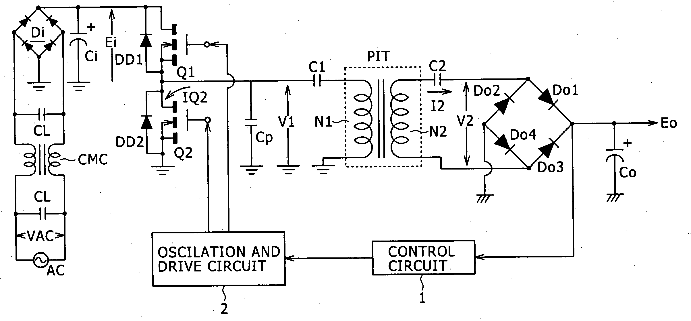
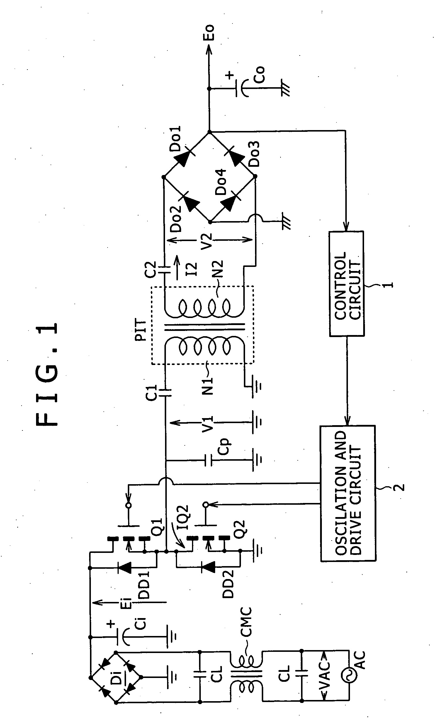
[0115]FIG. 1 is a circuit diagram illustrating a configuration example of a switching power supply circuit as the invention.

[0116] The power supply circuit shown in the drawing employs as its basic configuration, a configuration in which a separately-excited current resonant converter constructed by half-bridge connection is combined with a partial voltage resonant circuit.

[0117] In the power supply circuit, coupled to the commercial alternating-current power supply AC is a common mode noise filter formed of the filter capacitors CL and the common mode choke coil CMC.

[0118] To the commercial power supply AC, a full-wave rectifying and smoothing circuit formed of the bridge rectifier circuit Di and the smoothing capacitor Ci are coupled downstream from the noise filter.

[0119] The full-wave rectifying and smoothing circuit is fed with an AC voltage from the commercial power supply AC and performs full-wave rectifying operation, and thus the rectified and smoothed voltage Ei (DC inp...

second embodiment

[0235]FIG. 8 is a circuit diagram illustrating the configuration of a switching power supply circuit as the present invention.

[0236] The second embodiment in FIG. 8 employs full-bridge connection as the configuration of its switching converter, instead of half-bridge connection.

[0237] The same parts in FIG. 8 as those in FIG. 1 are given the same numerals, and description thereof will be omitted.

[0238] Referring to FIG. 8, in the full-bridge connection configuration, the half-bridge connected switching elements Q1 and Q2 are connected in parallel with half-bridge connected switching elements Q3 and Q4.

[0239] Damper diodes DD3 and DD4 that are body diodes are connected in parallel with the channel between the drain and source of the switching elements Q3 and Q4, respectively, similarly to the switching elements Q1 and Q2.

[0240] In addition, these full-bridge connected switching elements are coupled as follows to a primary-side series resonant circuit formed by connecting in serie...

third embodiment

[0250]FIG. 9 is a circuit diagram illustrating the configuration of a switching power supply circuit as the present invention.

[0251] The same parts in FIG. 9 as those in FIG. 1 are given the same numerals and will not be described below.

[0252] The third embodiment employs a configuration for switching the operation of the primary-side rectifier circuit between full-wave rectifying operation and voltage-doubling rectifying operation depending on the rated voltage of a commercial AC power supply. In addition, a voltage-doubler half-wave rectifier circuit is provided as the secondary-side rectifying and smoothing circuit.

[0253] On the primary side, a circuit formed of a smoothing capacitor Ci1 and a smoothing capacitor Ci2 that are serially connected is provided as the smoothing capacitor Ci that smoothes a rectified output from the bridge rectifier circuit Di provided for the commercial alternating-current power supply AC to thereby produce the rectified and smoothed voltage Ei. The...


PUM


Abstract

A wide-range compatible switching power supply circuit employs switching frequency varying control and allows enhancement of its AC to DC power conversion efficiency when a large AC input voltage is used. A coupled resonant circuit employing electromagnetic coupling by an isolation converter transformer is formed by providing a series resonant circuit both on the primary side and on the secondary side of the transformer. In order to achieve a unimodal output characteristic in the coupled resonant circuit, the length of a gap formed in a core of the isolation converter transformer is set to about 2.0 mm, and a coupling coefficient is set to about 0.8 or less. Thus, the switching frequency variable control range can be narrowed, which allows a wide-range compatible configuration. In addition, resonant frequencies of primary-side and secondary-side resonant circuits are set so that a requisite phase shift arises between a primary-side series resonant current and a secondary-side rectified current at least when an AC input voltage is 100 V and the load power is the maximum load power. Thus, the AC to DC power conversion efficiency when the AC input voltage VAC is 230 V can be enhanced.

Description

CROSS REFERENCE TO RELATED APPLICATIONS [0001] The present application claims priority from Japanese Patent Application No. JP 2005-001521 filed on Jan. 6, 2005, the disclosure of which is hereby incorporated by reference herein. BACKGROUND OF THE INVENTION [0002] The present invention relates to a switching power supply circuit included in various electronic apparatuses as a power supply. [0003] The present assignee has proposed various power supply circuits including a resonant converter on the primary side thereof. Japanese Patent Laid-open No. 2003-235259 discloses one example of the proposed power supply circuits. [0004]FIG. 12 is a circuit diagram illustrating one example of a switching power supply circuit that includes a resonant converter and is constructed based on any of the inventions that have been filed by the present assignee. [0005] The switching converter in the power supply circuit shown in FIG. 12 has a configuration in which a separately-excited current resonant ...

Claims


Application Information

Patent Timeline
IPC IPC(8): H02M3/335H02M3/28H02M7/5383
CPCH02M1/10H02M3/3385Y02B70/1433Y02B70/10A61H39/04A61H2205/125A61H2201/1269A61H2201/0119A61H2201/1685
Inventor YASUMURA, MASAYUKI
Owner SONY CORP
Learn More