Catadioptric Projection Objective

a catadioptric and objective technology, applied in the field of catadioptric projection objectives, can solve the problems of inability to complete achromatization, limited opportunity to correct chromatic errors, and substantially restricted refractive design forms, and achieve good image correction and favorable design.

Inactive Publication Date: 2008-02-14
CARL ZEISS SMT GMBH
View PDF6 Cites 32 Cited by
  • Summary
  • Abstract
  • Description
  • Claims
  • Application Information

AI Technical Summary

Benefits of technology

[0020]It is an object of the invention to provide a catadioptric projection objective which, with a favorable design, allows good correction of image errors. In particular, it should be possible to correct the Petzval sum and the chromatic aberrations under conditions which are favorable in terms of manufacturing technology.

Problems solved by technology

The form of the refractive design, however, is substantially constrained by two elementary image errors: the chromatic correction and the correction of the Petzval sum (image field curvature).
If only one refractive material is used (generally SiO2 for 193 nm, CaF2 for 157 nm) then the opportunity to correct the chromatic errors is very restricted.
Full achromatization cannot be carried out.
But this conflicts with the correction of the transverse chromatic aberration.
A disadvantage of the catadioptric design, however, is that it is necessary to operate either with off-axial object fields, that is to say an increased etendue (in systems with geometrical beam splitting) or with physical beam splitter elements, which generally cause problems with the polarization.
This can lead to problems with availability of space.
A disadvantage of such systems, however, is that the second refractive part again introduces chromatically and Petzval-undercorrected elements which need to be compensated for in the catadioptric part.

Method used


Image

  • Catadioptric Projection Objective
  • Catadioptric Projection Objective
  • Catadioptric Projection Objective

Examples


Embodiment Construction

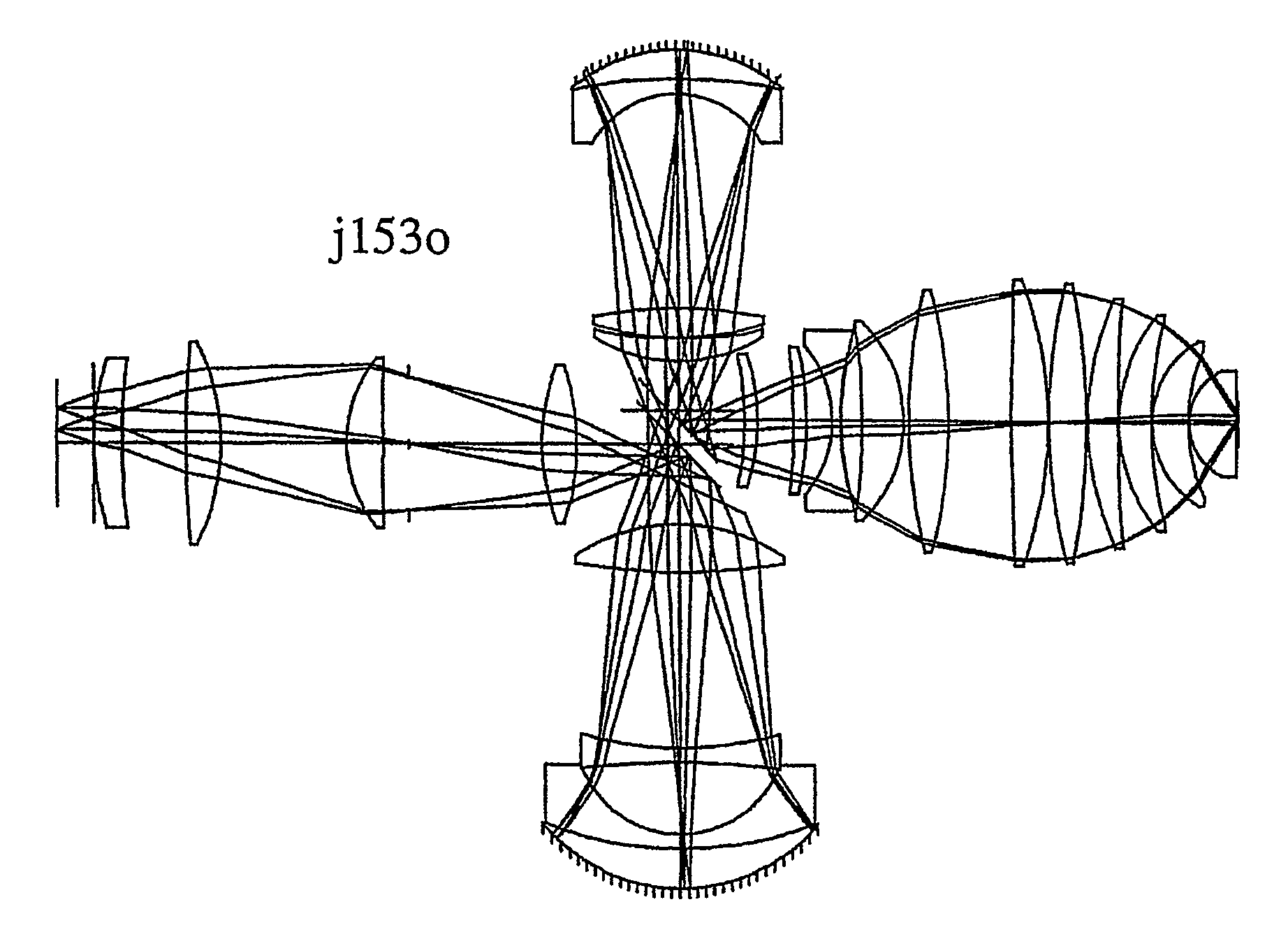
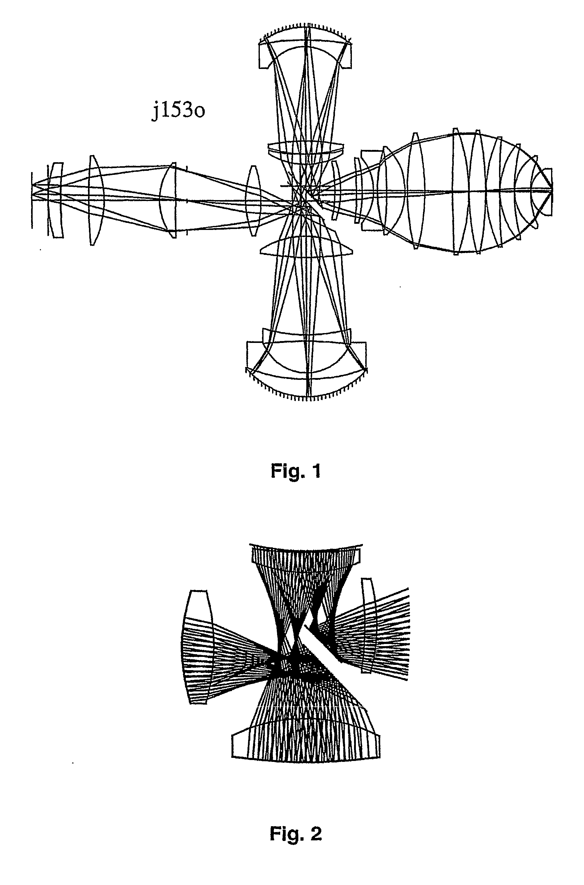
[0045]FIG. 1 shows a first embodiment of a projection objective according to the invention. FIG. 2 shows a detailed view of the region of the beam deflection device (folding arrangement or folding device).

[0046]This system has the following parts in the light propagation direction: from the reticle (object plane (on the left in the figure) the light propagates through the first refractive part (R1) onto a folding mirror (F1), which is located in the vicinity of the first intermediate image (ZB1). The first folding mirror F1 reflects the light into a first (downward pointing) catadioptric part (HOA1). This part may be aligned essentially horizontally during operation. Such objective parts are also referred to below as a horizontal arm (HOA). This HOA1 projects the light onto a second intermediate image (ZB2) in the vicinity of the folding mirror (F1, F2). The light then passes through the other second catadioptric part (HOA2), on the top in the drawing, which in turn generates an int...


PUM

PropertyMeasurementUnit
wavelengthsaaaaaaaaaa

Abstract

A catadioptric projection objective for projecting a pattern arranged in the object plane of the projection objective into the image plane of the projection objective, having: a first objective part for projecting an object field lying in the object plane into a first real intermediate image; a second objective part for generating a second real intermediate image with the radiation coming from the first objective part; a third objective part for generating a third real intermediate image with the radiation coming from the second objective part; and a fourth objective part for projecting the third real intermediate image into the image plane.

Description

BACKGROUND OF THE INVENTION[0001]1. Field of the Invention[0002]The invention relates to a catadioptric projection objective for projecting a pattern arranged in the object plane of the projection objective into the image plane of the projection objective.[0003]2. Description of the related Prior Art[0004]Such projection objectives are used in microlithography projection exposure systems in order to produce semiconductor components and other finely structured components. Their purpose is to project patterns of photomasks or lined plates, which will be generically referred to below as masks or reticles, onto an substrate coated with a photosensitive layer with maximal resolution on a reducing scale.[0005]In order to generate finer and finer structures, it is then necessary on the one hand to increase the numerical aperture (NA) of the projection objective on the image side and, on that the other hand, to use shorter and shorter wavelengths, preferably ultraviolet light with wavelengt...

Claims


Application Information

Patent Timeline
Patent Type & Authority Applications(United States)
IPC IPC(8): G02B17/08G03F7/20
CPCG02B13/143G02B17/08G03F7/70275G02B17/0892G03F7/70225G02B17/0812
Inventor SHAFER, DAVIDEPPLE, ALEXANDERDODOC, AURELIANULRICH, WILHELMSCHUSTER, KARL-HEINZ
Owner CARL ZEISS SMT GMBH
Why Eureka
Try Eureka