Correct image zoomable reflecting telescope with near stationary eyepiece

a technology of near-stationary eyepiece and correct image, which is applied in the field of telescopes, can solve the problems of more complex design, variable mirror aperture between telescopes, and increased complexity of external finder scopes

Active Publication Date: 2008-02-14
DUBY DANTE
View PDF5 Cites 7 Cited by
  • Summary
  • Abstract
  • Description
  • Claims
  • Application Information

AI Technical Summary

Benefits of technology

[0015]The present invention is a reflecting telescope which yields a correct upright image, has zoom capability intrinsic to the design, and can maintain the eyepiece at a constant comfortable position independent of the image viewing angles.

Problems solved by technology

Both of those disadvantages cause more of the incoming light to be blocked and cause mirror aperture variability from telescope to telescope.
Further consideration of these also shows in the case of the Fundingsland design an external finder scope is not practical so a second parabolic mirror is used between its main parabolic mirror and its flat aperture mirror for this purpose.
The addition of the second parabolic mirror makes the design more complex and increases cost.
And, since this upper turret can rotate and be tilted in nearly any direction, so too would the finder scope, making it difficult to use if pointing straight up or backwards.
The rotating turret design adds to the complexity of the telescope in addition to requiring a third mirror, both of which add to the cost.
Also, in the Fisher design, light passes through an objective lens before striking the flat mirror and parabolic mirror, requiring those mirrors to be more precise and therefore more expensive.

Method used


Image

  • Correct image zoomable reflecting telescope with near stationary eyepiece
  • Correct image zoomable reflecting telescope with near stationary eyepiece
  • Correct image zoomable reflecting telescope with near stationary eyepiece

Examples


Embodiment Construction

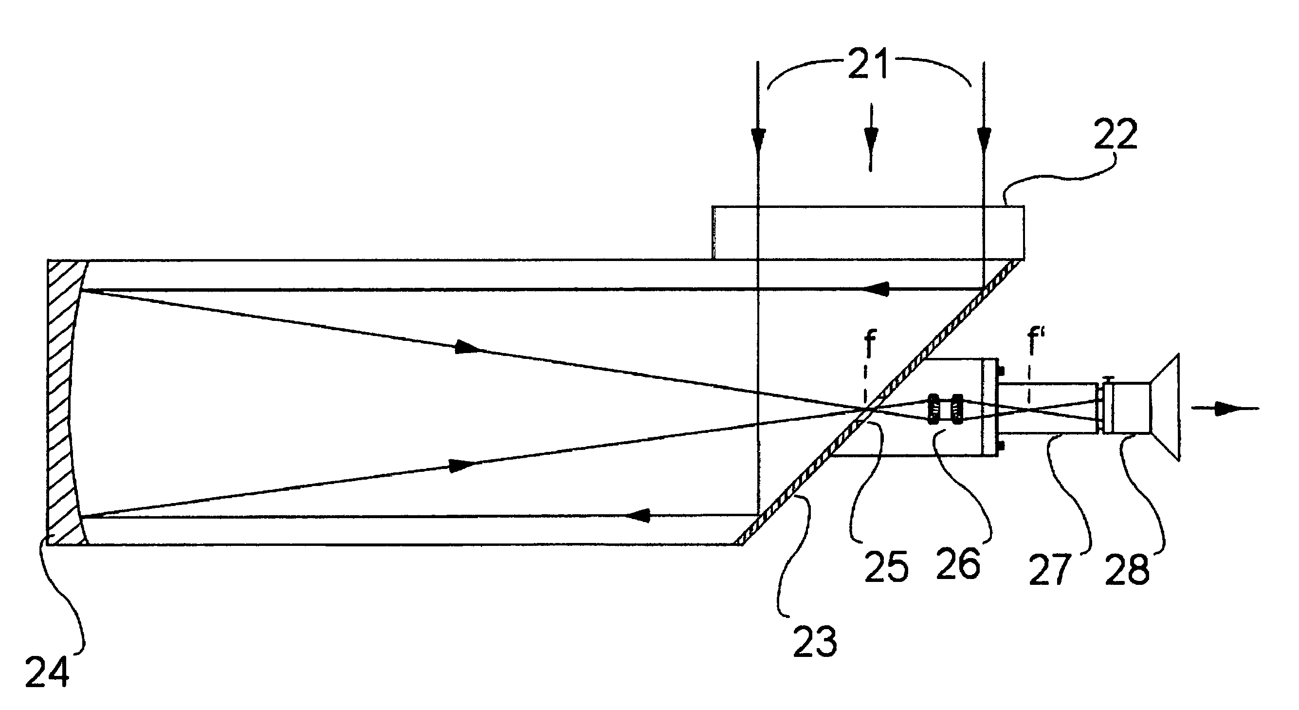
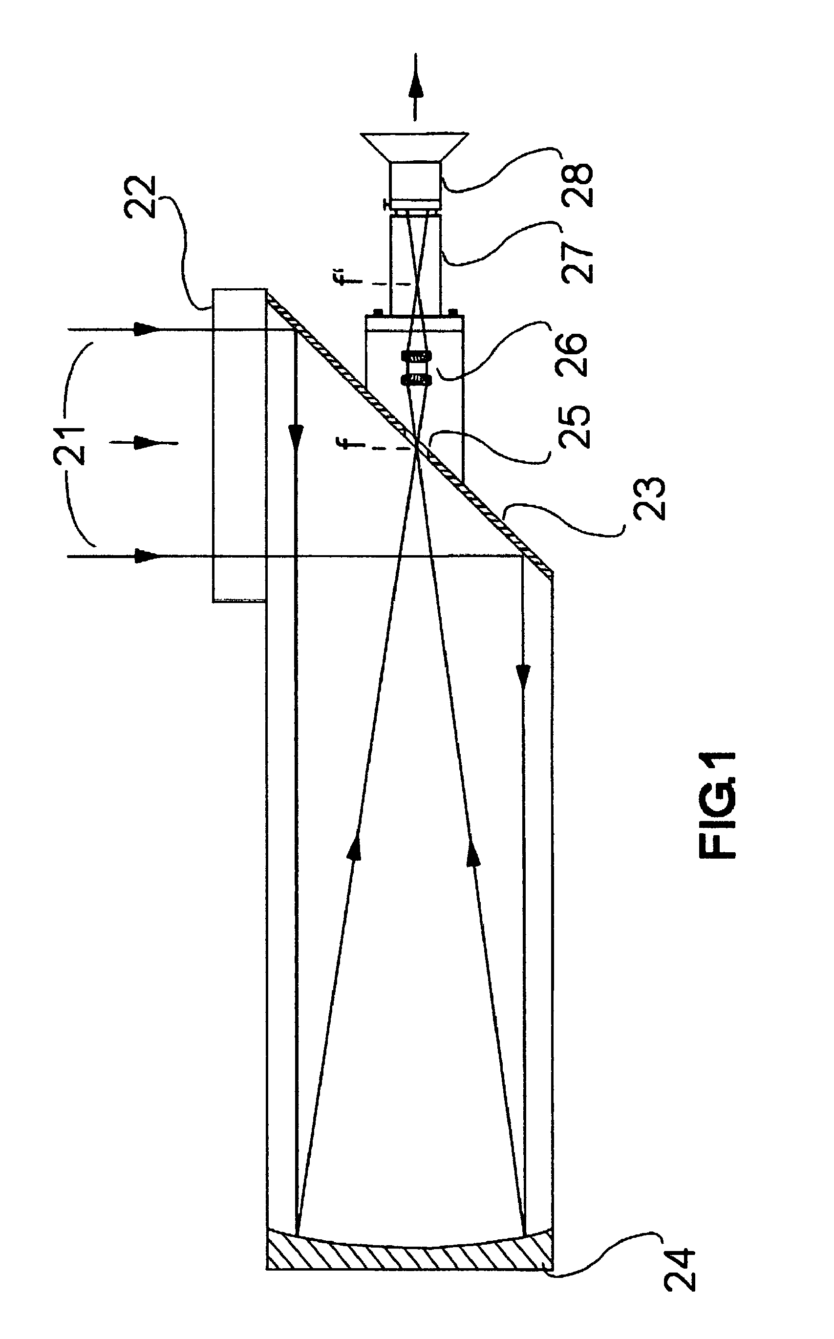
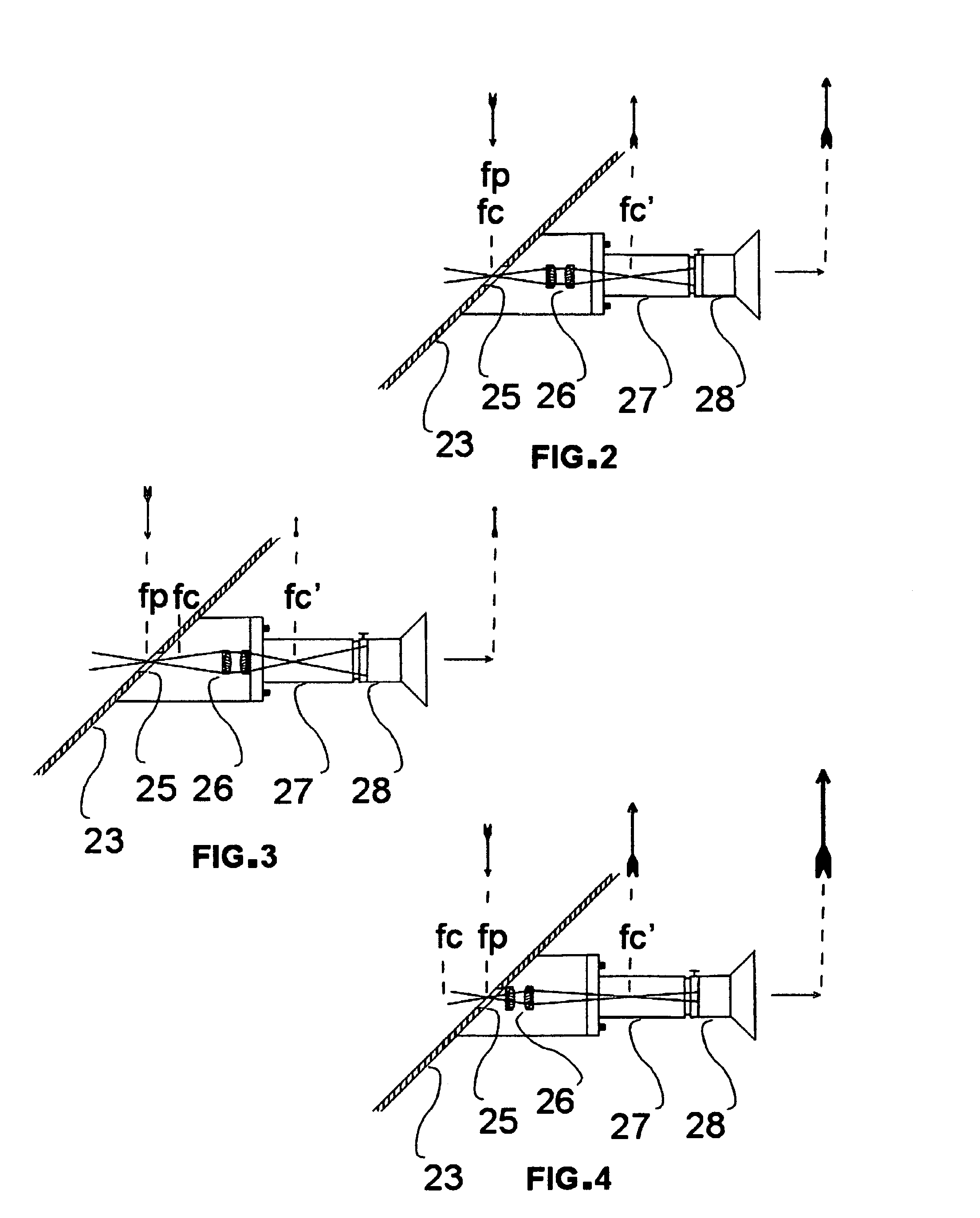
[0029]Referring to the drawings for a more detailed explanation of the preferred form of the invention, FIG. 1 shows the basic concept of the invention. Light 21 entering the aperture of the telescope 22 reflects off the flat aperture mirror 23 which redirects the light into the parabolic primary mirror 24. The light reflects off the primary mirror 24 and back through a small centrally located opening 25 in the flat aperture mirror 23. The focal point of this light f is just in front of the flat aperture mirror 23. The light then passes through the flat aperture mirror 23 and into the image correcting lens system 26. The focal point of the image correcting lens system 26 is coincident to the focal point of the primary mirror 24, in front of the opening 25 in the flat aperture mirror 23 at f, for the zero magnification zoom condition shown. The image correcting lens system 26 repositions the focal point to f, within the focuser range 27. The eyepiece 28 is then moved back and forth a...


PUM


Abstract

A correct image reflecting telescope with zoom capability comprised of a flat mirror, a parabolic primary mirror, and an image correcting system. The flat mirror reflects the incoming light from the telescope aperture into the parabolic primary mirror. The reflected light from the primary mirror passes back through a small centrally located opening in the flat aperture mirror and into an image correcting lens system. The image correcting system repositions the focal point of the primary mirror from a point in front of the flat aperture mirror to a point behind this mirror for observation with and eyepiece. The image correcting system makes the telescope useful in terrestrial as well as celestial applications and it can be moved with respect to the primary mirror such that a zoom feature results. This intrinsic zoom of the telescope allows an observer to use a single eyepiece in place of many, eliminates the need for an additional finder scope, and also makes the telescope useful in spotting scope applications. The eyepiece can remain at a stationary level for all observable directions.

Description

BACKGROUND OF THE INVENTION[0001]The present invention relates to telescopes, more specifically to an improved version of reflective telescope whereby the image is corrected intrinsic to the telescope optics. This feature combined with a nearly stationary eyepiece and zoom capability make it particularly useful for terrestrial as well as celestial use.[0002]This invention uses a specially designed telescope mount of my co-pending application. This mount has multiple degrees of freedom to accommodate the additional range of motion requirements and can easily be used in either a horizontal or vertical manner depending on individual comfort preferences and telescope size.[0003]One object of the invention is to improve the optical performance of a reflecting telescope over that of the Newtonian, Cassegrain, Gregorian, Maksutov and Schmidt-Cassegrain types. This optical advantage results from blocking less of the incoming light then these other telescope types. These other telescopes in ...

Claims


Application Information

Patent Timeline
Patent Type & Authority Applications(United States)
IPC IPC(8): G02B23/00
CPCG02B17/0896G02B17/08
Inventor DUBY, DANTE
Owner DUBY DANTE
Why Eureka
Try Eureka