Heating Device for Fuel

a heating device and fuel technology, applied in the direction of combustion-air/fuel-air treatment, lighting and heating equipment, and heating arrangements for immersion, can solve the problem of no longer ensuring the proper functioning of the internal combustion engine, and achieve the effect of preventing a short circui

Inactive Publication Date: 2008-02-14
MANN HUMMEL GMBH
View PDF9 Cites 14 Cited by
  • Summary
  • Abstract
  • Description
  • Claims
  • Application Information

AI Technical Summary

Benefits of technology

[0013] Another advantage can be achieved by making the carrier body of an electrically conductive material, so that it has not only a supporting or carrying function but is also electrically conductive and enables current to flow through the heating element. There is preferably a direct contact between the heating element and the carrier body, so that no additional electrically conductive connections are necessary between the carrier body and the heating element. In this embodiment, the carrying body not only carries and protects the element but also acts as an electric conductor.
[0014] To close the circuit, it is advantageous to provide a contact element formed separately from the carrier body and in electrical contact with the heating element. A closed circuit is obtained via the carrier body, the heating element and the additional contact element. The carrier body and the contact element are connected to different poles of the electrical circuit and are electrically isolated from each other to prevent a short circuit.

Problems solved by technology

If the fuel is not heated, the fuel lines and fuel filters become clogged, so that proper functioning of the internal combustion engine is no longer ensured.

Method used


Image

  • Heating Device for Fuel
  • Heating Device for Fuel
  • Heating Device for Fuel

Examples


Embodiment Construction

[0030] In the figures like parts are identified by the same reference numerals.

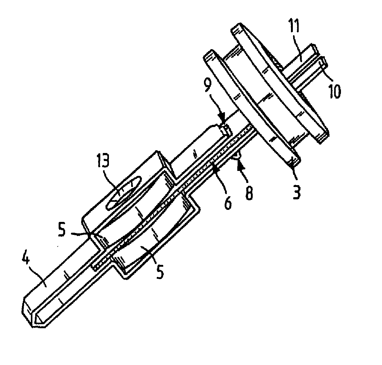
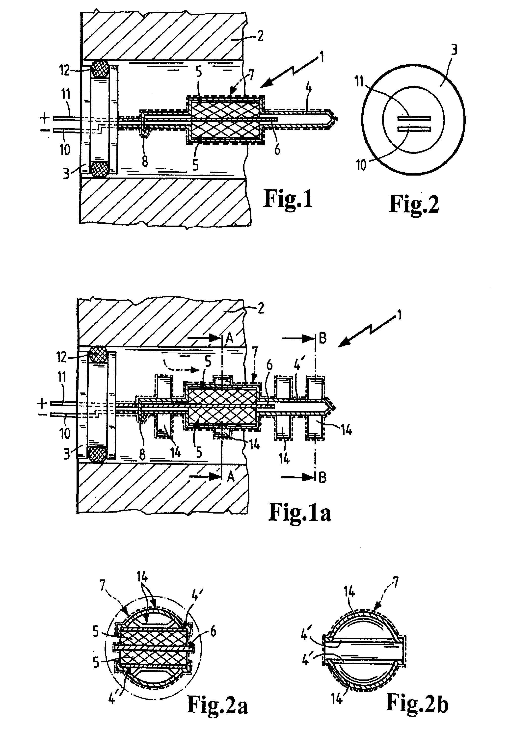
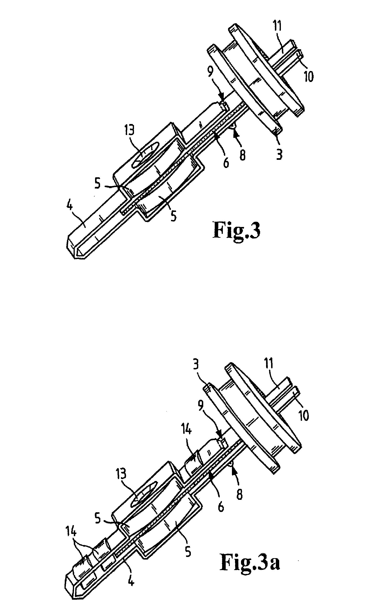
[0031]FIG. 1 shows the fuel heating device 1 when installed in a housing 2 of a unit, such as a fuel filter, for example. The heating device 1 comprises a disk-shaped base 3 holding the carrier body 4, which is formed of sheet metal. The base 3 is made of an electrically insulating material, particularly a ceramic coating or adhesive, into which the plate-shaped carrier body 4 is cast. The base 3 held inside the housing 2 is sealed in relation to the housing by means of a sealing ring 12.

[0032] In the area of its free end face, the carrier body 4 is bent to form a holding space between two side faces, into which two superimposed electric heating elements 5 are inserted. Each side piece of the carrier body 4 has an indentation with a heating element 5 inserted in each. In this manner, the heating elements 5 are fixed in longitudinal and transverse direction of the carrier body 4. In vertical direction, t...


PUM


Abstract

A heating device for fuel comprising an electric heating element (5), which is mounted on a carrier body (4). The carrier body (4) surrounds the heating element (5), and an insulating protective layer coating (7) is applied to the carrier body.

Description

CROSS REFERENCE TO RELATED APPLICATIONS [0001] This application is a continuation of international patent application no. PCT / EP2006 / 060324, filed Feb. 28, 2006 designating the United States of America and published in German on Sep. 14, 2006 as WO 2006 / 094921, the entire disclosure of which is incorporated herein by reference. Priority is claimed based on Federal Republic of Germany patent application no. DE 10 2005 011 182.3, filed Mar. 9, 2005.BACKGROUND OF THE INVENTION [0002] The invention relates to a heating device for fuel, particularly diesel fuel for a motor vehicle. [0003] U.S. Pat. No. 6,493,508 (=DE 199 55 206) discloses a fuel filter for internal combustion engines with an integrated fuel heating unit to heat the fuel of the internal combustion engine. The fuel is heated to keep it liquid at low temperatures below 0° C. because components such as paraffins contained particularly in diesel fuels become viscous or solid at these temperatures. If the fuel is not heated, t...

Claims


Application Information

Patent Timeline
Patent Type & Authority Applications(United States)
IPC IPC(8): B60L1/02H05B3/78
CPCF02M31/125Y02T10/126H05B3/44H01C1/028Y02T10/12
Inventor FASOLD, MICHAELBAUER, SASCHA
Owner MANN HUMMEL GMBH
Why Eureka
Try Eureka