
Floaing platform with non-uniformly distributed load and method of construction thereof

a floating platform and load technology, applied in waterborne vessels, special-purpose vessels, constructions, etc., can solve the problems of large-scale offshore oil and gas fields, the risk of increasing the level of the world ocean, and the difficulty of ensuring the safety of the floating platform,

Inactive Publication Date: 2008-02-14
SHARAPOV SERGEY
View PDF19 Cites 37 Cited by
  • Summary
  • Abstract
  • Description
  • Claims
  • Application Information

AI Technical Summary

Benefits of technology

[0032]It is an object of the present invention to provide a floating platform that can be assembled from standard hollow prefabricated structural elements having means for adjusting buoyancy. It is another object to provide a floating platform of a large surface area wherein the unified center of masses of the loads supported by the platform always remains in the same position that corresponds to horizontally counterbalanced state of the platform, even during assembling of the platform and construction of on-board facilities. It is still another object to provide a floating platform wherein all the moments created by all the loads supported by the floating platform relative to the aforementioned center of masses are counterbalanced. It is another object to provide a method of assembling a floating platform that is anchored to the sea bottom and can be deployed in shallow as well as in deep waters in such a manner that the unified center of masses of the construction elements and loads supported by the platform remain in the permanent position that maintains the platform in a horizontally counterbalanced state and in such a manner that all moments of the loads supported by the floating platform are in an equilibrium.

Problems solved by technology

These new trends are associated with the risk of increase in the level of the world ocean in connection with melting of Arctic an Antarctic ice packs because of global warming.
The development of deep water offshore oil and gas fields present substantial challenges to the petroleum industry.
While relatively stable, such fixed platforms are typically limited to shallow waters, i.e., depths of about 500 feet (150 m) or less.
Although floating platforms are more complex to operate because of their greater movement in response to wind and wave conditions, they are capable of operating at substantially greater depths than fixed platforms, and are also more mobile, and hence, easier to move to other offshore well sites.
However, the offshore installation of their equipment deck requires the use of a heavy-duty crane barge.
Additionally, they have a relatively low hull efficiency, and their off-shore hook-up and connection procedures are relatively time-consuming and expensive.
The motions of these types of semi-submersible platforms are relatively large, and accordingly, they require the use of “catenary” risers (either flexible or semi-rigid), extending from the seafloor to the work platform because they are not capable of supporting the other types of risers, e.g., top-tensioned vertical risers (“TTRs”) that are typically employed in deep water operations.
Additionally, the use of multiple columns entails higher fabrication costs, and the leg wells are relatively wasteful of useful equipment deck area.
These platforms with submerged floating body are easily maneuverable and can readily be transported to their destination point, but the two parallelly disposed displacement elements or bodies react to a significant extent to underwater currents and are difficult to maintain in position.
Another problem may be associated with a variable load distribution.
The floating airport may encounter a problem, associated with change in distribution of load caused by rearrangement of planes or transport.
The topsides are located offset from the central region of the transporter, creating an uneven load distribution.

Method used


Image

  • Floaing platform with non-uniformly distributed load and method of construction thereof
  • Floaing platform with non-uniformly distributed load and method of construction thereof
  • Floaing platform with non-uniformly distributed load and method of construction thereof

Examples


Embodiment Construction

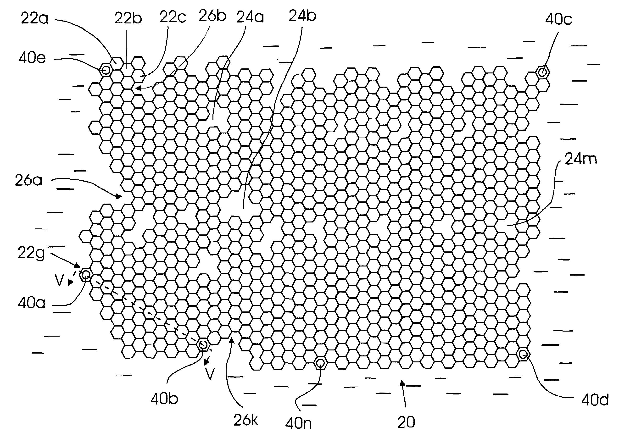
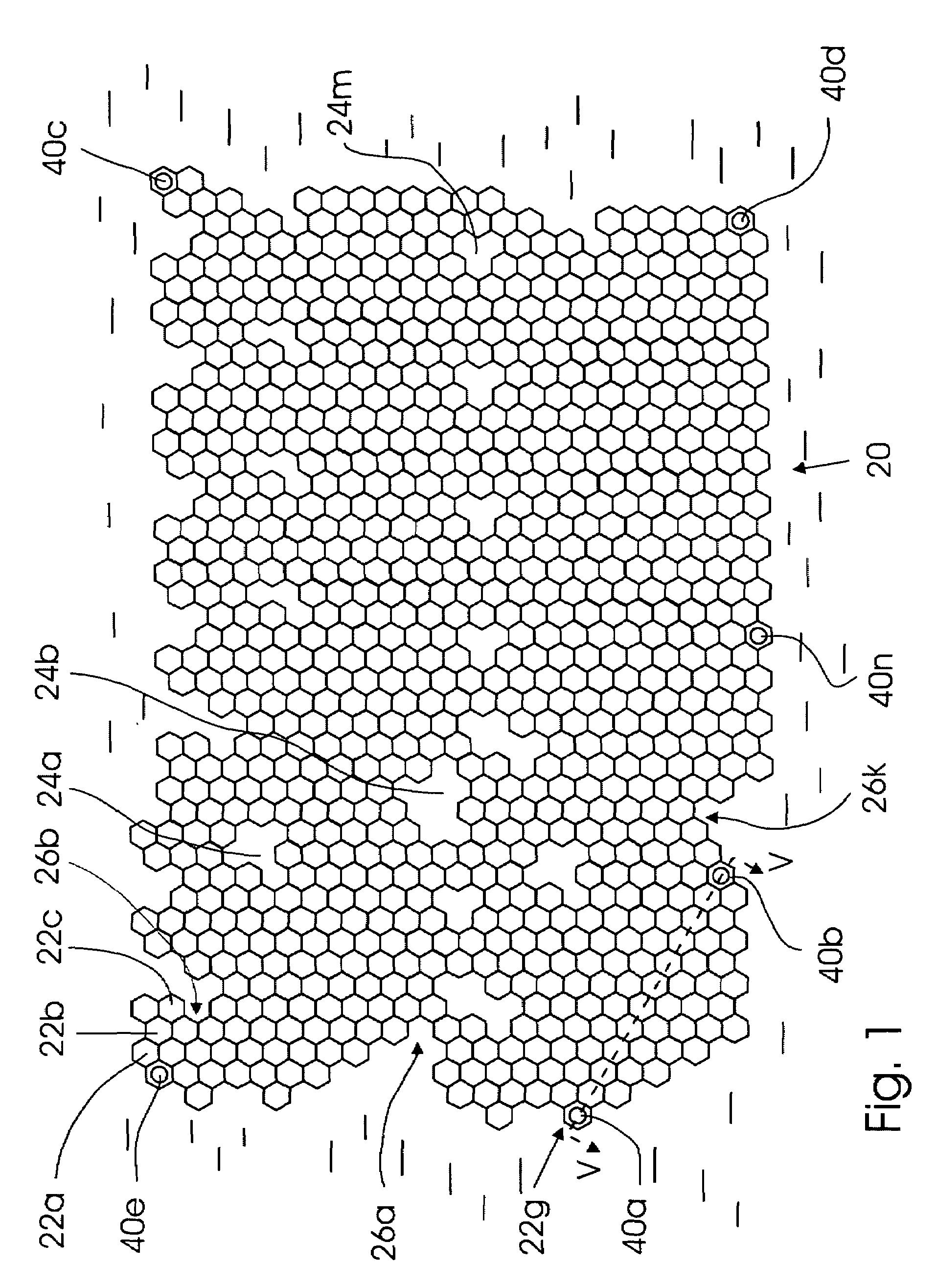
[0034]A general top view of the floating platform of the invention is shown in FIG. 1. It can be seen that in the top view the floating platform that as a whole is designated by reference numeral 20 comprises a mosaic of standardized floating structural elements 22a, 22b, . . . 22n which in a top view and in a transverse cross section have a shape that allow packing of said elements into a monolithic body with the top surfaces of the elements forming a continuous surface. An example of such a shape is a hexagonal cross section. In a top view as well as in a transverse cross-section the standardized floating structural elements 22a, 22b, . . . 22n (hereinafter referred to as structural elements) may have a triangular, square, or another shape, but the hexagonal shape is preferable. The mosaic of the structural elements shown in FIG. 1 is formed by the upper end faces of the structural elements 22a, 22b, . . . 22n, and the elements themselves will be described in detail later. It can ...


PUM


Abstract

The floating platform of the invention is intended for supporting industrial, commercial, cultural, and dwelling structures and is suitable for deployment in shallow as well as in deep waters, The platform is assembled from prefabricated hollow structural elements in such a way that the unified center of masses of the loads that consist of a plurality of arbitrarily distributed loads of different masses supported by the platform is always maintained in the same position whereby the platform is always maintained in a horizontally counterbalanced position. This is achieved by locally adjusting the buoyancy of the structural elements. Furthermore, the loads are positioned on the platform so that moments created by these loads relative to the aforementioned unified center of masses are equal. This allows maintaining the loads on the platform in equilibrium.

Description

FIELD OF THE INVENTION[0001]The invention relates to floating structures, in particular, to offshore structures with non-uniform distribution of load, such as floating islands that may support oil and gas recovery equipment, airports, industrial installations, buildings, dwelling houses, stores, and other facilities required for industrial activity and urban life.[0002]Various floating offshore structures are well known since long ago and find use in development of deep-water oil and gas fields, such as are found in the Gulf of Mexico and the North Sea. However, in addition to offshore recovery of natural resources, recently new trends appeared in the field of development of floating structures. These new trends are associated with the risk of increase in the level of the world ocean in connection with melting of Arctic an Antarctic ice packs because of global warming.[0003]Although the floating offshore structure of the invention relates to a floating platform with industrial and d...

Claims


Application Information

Patent Timeline
IPC IPC(8): B63B35/44
CPCB63B35/44
Inventor SHARAPOV, SERGEY
Owner SHARAPOV SERGEY
Features
  • Generate Ideas
  • Intellectual Property
  • Life Sciences
  • Materials
  • Tech Scout
  • Unparalleled Data Quality
  • Higher Quality Content
  • 60% Fewer Hallucinations
Learn More