Heat pump cycle device

a cycle device and heat pump technology, applied in heat pumps, indirect heat exchangers, lighting and heating apparatus, etc., can solve problems such as fog on the windshield of vehicles, and achieve the effect of effective improvement of cycle efficiency

Inactive Publication Date: 2008-02-21
DENSO CORP
View PDF3 Cites 73 Cited by
  • Summary
  • Abstract
  • Description
  • Claims
  • Application Information

AI Technical Summary

Benefits of technology

[0007] In view of the foregoing problems, it is a first object of the present invention to provide a heat pump cycle device which can effectively improve cycle efficiency.

Problems solved by technology

However, because the interior heat exchanger is used for both the evaporator and the refrigerant radiator, condensed water generated on the interior heat exchanger during the cooling operation mode or a dehumidifying operation mode is heated and evaporated in the heating operation mode, and is blown into the vehicle compartment together with air, thereby easily causing fog on a windshield of the vehicle.

Method used


Image

  • Heat pump cycle device
  • Heat pump cycle device
  • Heat pump cycle device

Examples


first embodiment

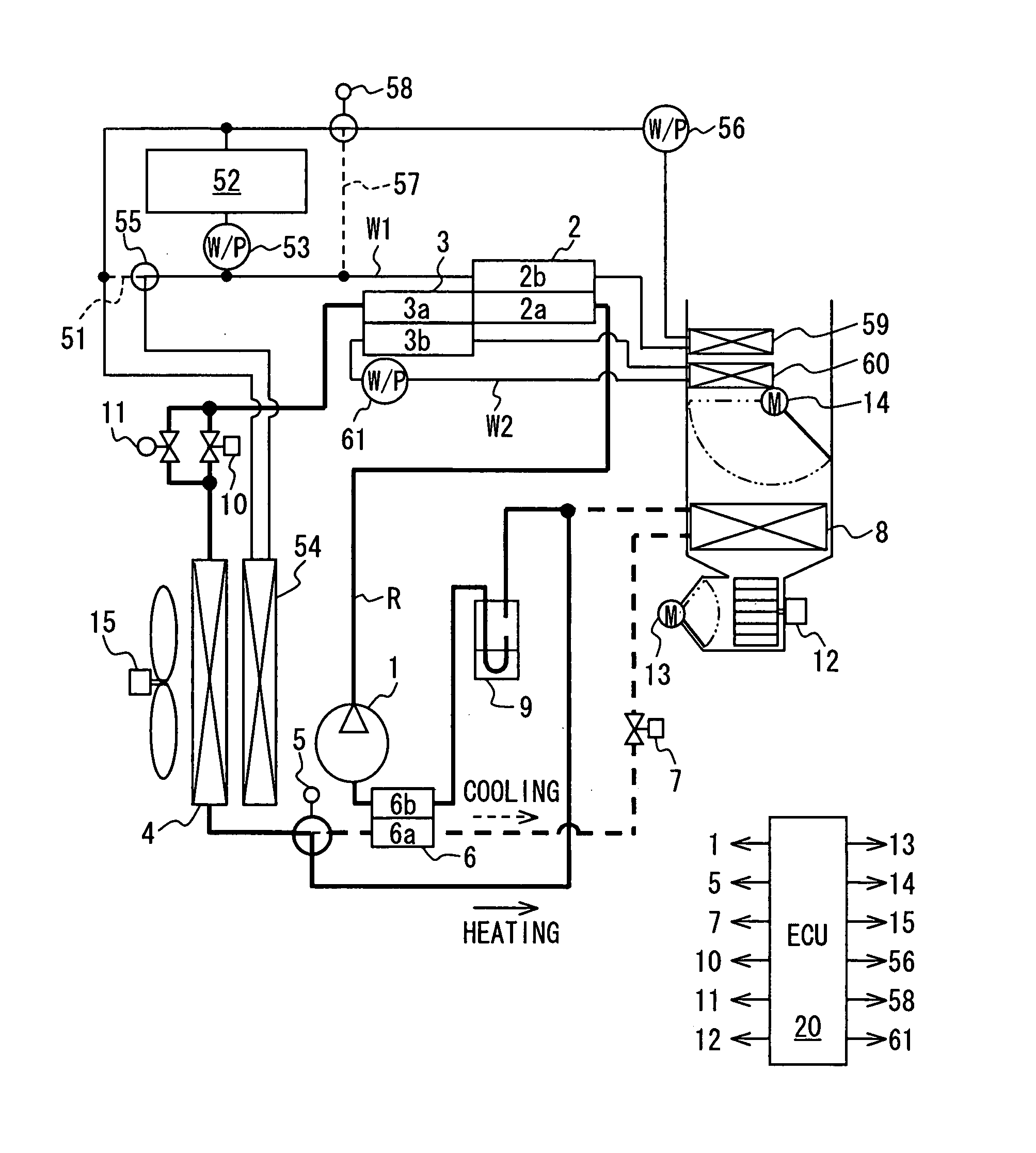
[0022] A first embodiment of the present invention will be now described with reference to FIGS. 1 to 3. In this embodiment, a heat pump cycle device of the present invention is typically used for an air conditioner for a vehicle, and is provided to improve a cycle efficiency while having an auxiliary heating function.

[0023] As shown in FIG. 1, the heat pump cycle device includes a refrigerant cycle R in which refrigerant circulates, a first water circuit W1 in which engine-cooling water as a first fluid circulates, and a second water circuit W2 in which water as a second fluid circulates. In this embodiment, the first water circuit W1 and the second water circuit W2 are formed independently from each other. However, the first water circuit W1 and the second water circuit W2 may be partially joined with each other.

[0024] First, the refrigerant cycle R will be described. In the refrigerant cycle R of FIG. 1, a compressor 1 draws and compresses low-pressure side refrigerant, and dis...

second embodiment

[0065]FIG. 4 is a schematic diagram showing a heat pump cycle device according to a second embodiment of the present invention. In the second embodiment, a third heat source 62 is additionally provided in the second water circuit W2, compared with the above-described first embodiment.

[0066] The third heat source 62 is an auxiliary machine (heat generating unit) such as an inverter and an electronic member of a hybrid vehicle, which generates heat when being operated. The auxiliary machine is located in the second water circuit W2 to recover exhaust heat. Furthermore, an auxiliary radiator 63 may be located in the second water circuit W2. In this embodiment, because the third heat source 62 is located in the second water circuit W2 in which the second fluid (water) circulates, the air heating efficiency of the second water heater 60 in the second water circuit W2 can be further improved.

[0067] The heat quantity supplied from the second heat source (e.g., engine) 52 is normally larg...


PUM


Abstract

A heat pump cycle device includes a compressor for drawing and compressing refrigerant, a first high-pressure heat exchanger located for heating a first fluid circulating in a first fluid circuit using high-pressure refrigerant discharged from the compressor, a second high-pressure heat exchanger for heating a second fluid circulating in a second fluid circuit using the high-pressure refrigerant flowing out of the first high-pressure heat exchanger, a first heating heat exchanger located to heat a third fluid using the first fluid, a second heating heat exchanger located to heat the third fluid using the second fluid, a decompression unit located to decompress the high-pressure refrigerant flowing out of the second high-pressure heat exchanger, and a low-pressure heat exchanger for evaporating low-pressure refrigerant decompressed by the decompression unit. Because the first and second high-pressure heat exchangers are located, cycle efficiency can be improved.

Description

CROSS REFERENCE TO RELATED APPLICATION [0001] This application is based on Japanese Patent Application No. 2006-106788 filed on Apr. 7, 2006, the contents of which are incorporated herein by reference in its entirety. BACKGROUND OF THE INVENTION [0002] 1. Field of the Invention [0003] The present invention relates to a heat pump cycle device in which heat is transported from a low-temperature side to a high-temperature side. [0004] 2. Description of the Related Art [0005] U.S. Pat. No. 6,574,977 B2 (corresponding to JP-A-2002-98430) describes a heat pump cycle device that includes a first high-pressure heat exchanger in which high-pressure refrigerant is heat-exchanged with a first fluid, and a second high-pressure heat exchanger in which high-pressure refrigerant flowing out of the first high-pressure heat exchanger is heat-exchanged with a second fluid having a temperature lower than that of the first fluid. Accordingly, a heat quantity obtained from the heat pump cycle device is ...

Claims


Application Information

Patent Timeline
Patent Type & Authority Applications(United States)
IPC IPC(8): F25B30/00
CPCB60H1/00342B60H1/00899B60H2001/00928B60H2001/00949F25B9/008F25B29/003F28D7/0083F25B40/00F25B2309/061F25B2400/0411F25B2600/2507F28D7/0025F28D7/0066F25B39/04
Inventor ITOH, SATOSHI
Owner DENSO CORP
Why Eureka
Try Eureka