Brake Disk, In Particlular for a Vehicle

a technology for brake disks and vehicles, applied in brake types, mechanical equipment, manufacturing tools, etc., can solve the problems of brake disk wear, brake disk wear, and brake disks are subjected to particularly high loads, so as to reduce the subsegment width, reduce and increase the wear of brake disks

Inactive Publication Date: 2008-02-21
KNORR-BREMSE SYST FUER NUTZFAHRZEUGE GMBH
View PDF12 Cites 33 Cited by
  • Summary
  • Abstract
  • Description
  • Claims
  • Application Information

AI Technical Summary

Benefits of technology

[0020] A systematic non-uniform wearing of the brake disk, conditioned, for example, by geometry and material properties of the brake pad, can be counteracted by a corresponding partial change in ratios of expansion joint width to subsegment width. An enlargement of the expansion joint leads to a reduction in subsegment width, which leads to an increase in brake disk wear. Cor

Problems solved by technology

When used in commercial vehicles, the brake disks are subjected to particularly high loads.
Frictional pressing against the brake pads, which usually act bilaterally upon the brake disk, generates frictional heat, which leads to a rise in temperatures in the brake pads and in the brake disk.
The cause of these differences is the inhomogeneous contact between the friction surfaces of the contacting brake pad and the brake disk.
This can give rise to crack formations in the brake surface, which, in the event of frequent high thermal load, can lead in extreme cases to tearing of the brake disk.
These tensile stresses can be greater than the tensile strength of the material, which then leads to cracking problems, particularly when the brake disks, as is common, are made of cast iron.
However, these grooves have small depths, which,

Method used


Image

  • Brake Disk, In Particlular for a Vehicle
  • Brake Disk, In Particlular for a Vehicle
  • Brake Disk, In Particlular for a Vehicle

Examples


Embodiment Construction

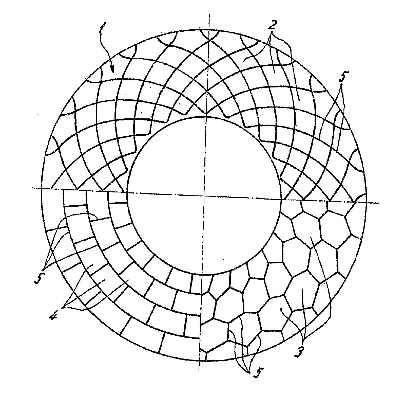
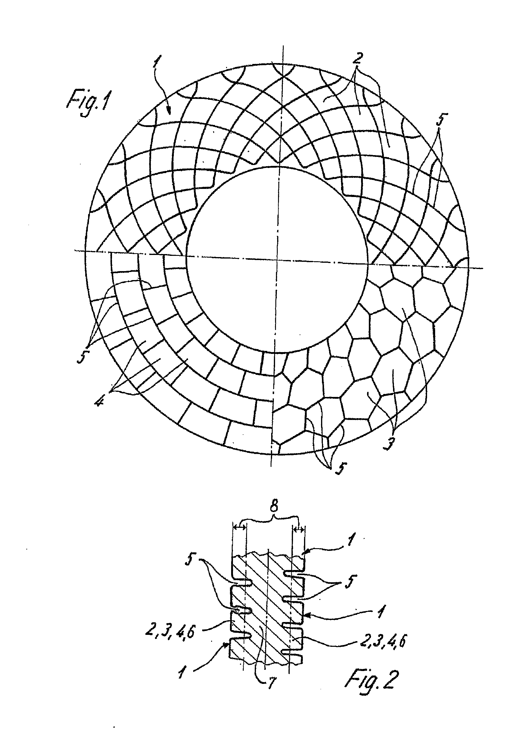
[0035] In FIGS. 1, 3, 4, and 5, brake disks for vehicles are respectively represented. Each disk has, on its sides, annular friction surfaces 1 (FIG. 2), against which, for braking, a brake pad (not represented) can be pressed.

[0036] In the present illustrative embodiments, the two friction surfaces 1 are joined together by a continuous brake disk core 7, so that the brake disk is in one piece. In principle, the possibility also exists of providing the brake disk with two thermally separated friction surfaces 1, in which case the internally ventilated brake disk is provided with cooling ducts between the two friction surfaces 1.

[0037] The friction surface 1 has a multiplicity of at least partially physically separated subsegments 2, 3, 4, and 5, which, as illustrated by FIGS. 1, 3, 4, and 5, can differ in terms of contouring.

[0038] The upper half of the brake disk shown in FIG. 1 shows subsegments 2, which have, in the broadest sense, a rhombic contour and are respectively separa...


PUM

PropertyMeasurementUnit
Diameteraaaaaaaaaa
Sizeaaaaaaaaaa
Widthaaaaaaaaaa

Abstract

A brake disc for a vehicle has at least one annular friction surface provided on at least one outer face of the disc to which a brake pad can be applied for braking purposes. The friction surface has a large number of subsegments, at least some of which are physically separated from one another by expansion joints. The brake disc is configured in such a way that the depth of the expansion joints is greater than the permissible rate of wear of the friction surface.

Description

[0001] This application is a continuation of international application PCT / EP2006 / 001829, filed Feb. 28, 2006, the entire disclosure of which is incorporated herein by reference and which, in turn, claims priority of German patent application 10 2005 009 744.8, filed Mar. 3, 2005.BACKGROUND AND SUMMARY OF THE INVENTION [0002] The present invention relates to a brake disk for a vehicle having at least one annular friction surface, provided on at least one outer side, against which a brake pad can be pressed for braking purposes, and in which the friction surface consists of a multiplicity of subsegments that are at least partially physically separated from one another by expansion joints. [0003] Brake disks find use in many fields of application. When used in commercial vehicles, the brake disks are subjected to particularly high loads. [0004] Frictional pressing against the brake pads, which usually act bilaterally upon the brake disk, generates frictional heat, which leads to a ris...

Claims


Application Information

Patent Timeline
IPC IPC(8): F16D65/12
CPCF16D65/12Y10T29/49826F16D2069/004
Inventor BAUMGARTNER, JOHANNPAHLE, WOLFGANGIRASCHKO, JOHANN
Owner KNORR-BREMSE SYST FUER NUTZFAHRZEUGE GMBH
Why Eureka
Try Eureka