Remote controlling system for electric device

a technology of remote control and electric devices, applied in the direction of electric controllers, program control, instruments, etc., can solve the problems of increasing the cost of production, difficult to set up the network environment, and the inability to remotely control the washing machine, so as to reduce the capacity of the whole component, improve the reception of signals, and facilitate the operation of electric devices.

Inactive Publication Date: 2008-02-21
LG ELECTRONICS INC
View PDF6 Cites 25 Cited by
  • Summary
  • Abstract
  • Description
  • Claims
  • Application Information

AI Technical Summary

Benefits of technology

[0017] Another object of the present invention is to provide a remote controlling device which enables the user to easily control operations of electric devices by displaying states of the electric devices before controlling the operations of the electric devices.
[0018] Yet another object of the present invention is to provide a remote controlling device which can reduce the capacity of the whole components and improve reception of signals.
[0019] Yet another object of the present invention is to provide a remote controlling device which can guarantee mobility in its installation position through wireless communication.

Problems solved by technology

Especially, researchers have made efforts to apply such a technology to a product which performs one operation for a relatively long time, such as the washer and the dryer.
In the case that the power supply of the washer is cut, the washer cannot be remotely controlled.
As a result, the unit cost of production increases.
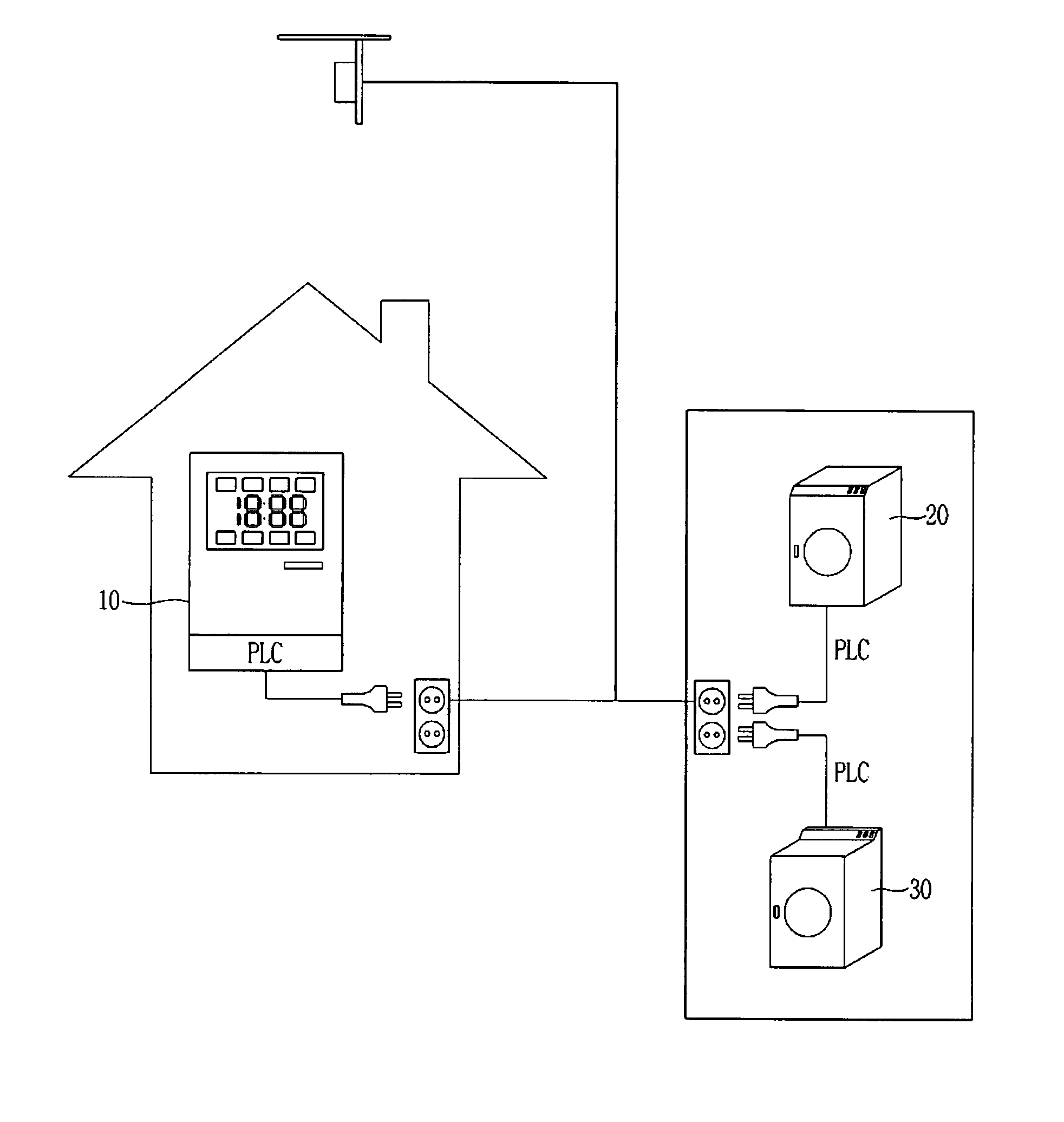
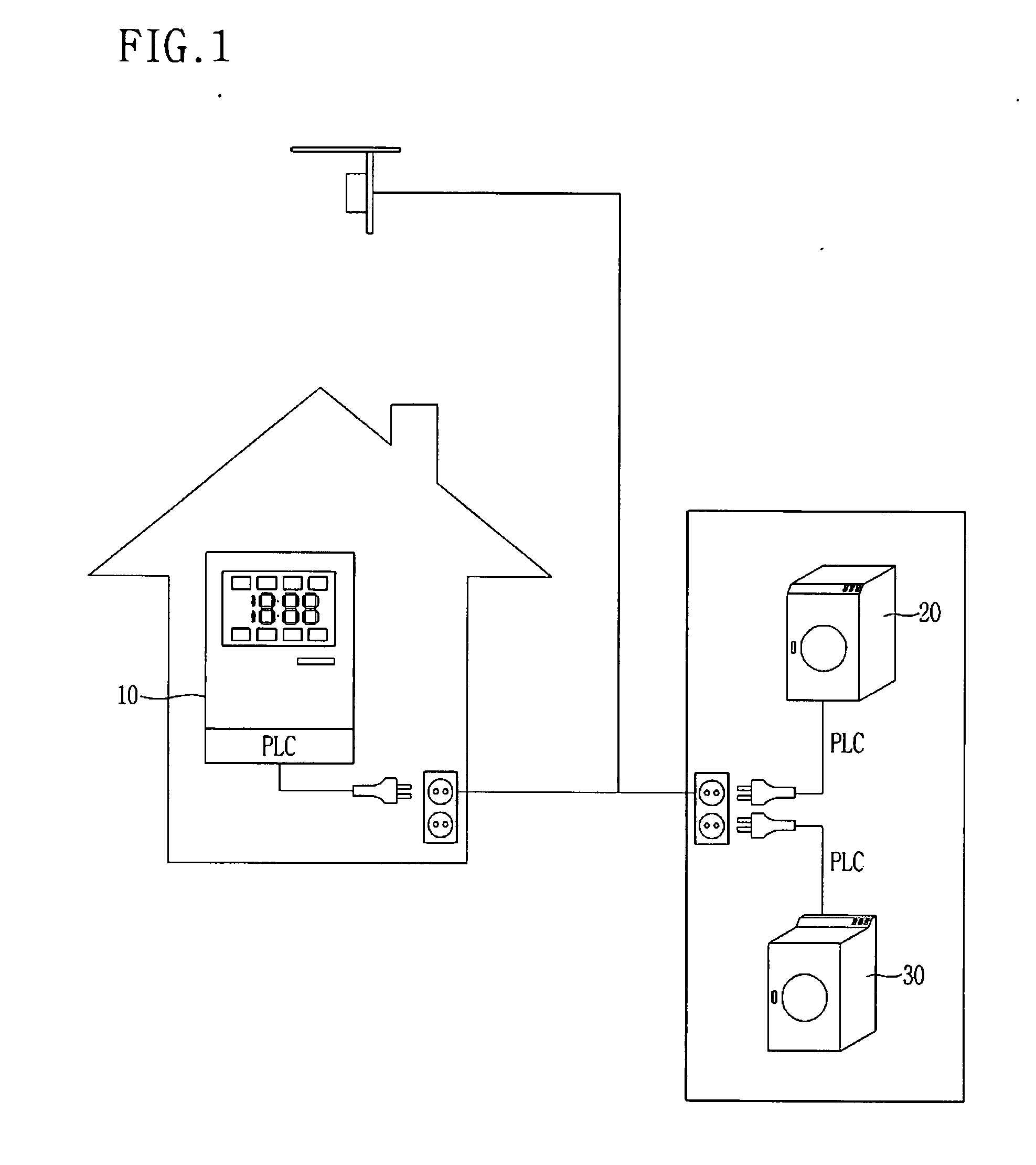
Moreover, when the washer and the dryer are installed in the outside warehouse or the underground washing room, it is difficult to set up the network environment.
In addition, the user cannot continuously check an error state which may occur during the operation.
Accordingly, although the washer or the dryer is not operated due to an error generated in the washing or drying operation, the user does not recognize the error and leaves the washer or the dryer in the error state.
It is also inconvenient for the user to go to the washer or the dryer and input the operation command.
Therefore, in the case that an error occurs in the product which has not been selected by the user, the monitoring device 10 cannot inform the user of the error state.

Method used


Image

  • Remote controlling system for electric device
  • Remote controlling system for electric device
  • Remote controlling system for electric device

Examples


first embodiment

[0059]FIG. 8 is a flowchart showing sequential steps of a remote controlling method in accordance with the present invention.

[0060] In detail, in step S81, the microcomputer 160 of the remote controlling device 100 decides whether electric device selection has been inputted through the input unit 110. If so, the microcomputer 160 goes to step S83, and if not, the microcomputer 160 goes to step S82.

[0061] In step S82, the microcomputer 160 reads the set information stored in the storing unit 150, and displays the preset electric device on the display unit 140 for state display or operation control. Here, the microcomputer 160 can simply display the name or icon of the preset electric device.

[0062] In step S83, the microcomputer 160 displays the electric device corresponding to the selection input from the input unit 110 on the display unit 140 in the same manner as that of step S82.

[0063] In step S84, the microcomputer 160 decides whether the state request for the selected or pres...

second embodiment

[0072]FIG. 9 is a flowchart showing sequential steps of a remote controlling method in accordance with the present invention.

[0073] In detail, in step S91, the microcomputer 160 acquires the electric device selection input from the input unit 110. In step S91, if the microcomputer 160 controls the operation of the electric device whose current state is displayed, this selection step is not required.

[0074] In step S92, the microcomputer 160 acquires the operation control input for the selected electric device from the input unit 110. If the microcomputer 160 does not acquire the operation control input, the microcomputer 160 decides that the user wants state display, and goes to {circle around (a)} of FIG. 8 to display the state of the electric device. If the microcomputer 160 acquires the operation control input, it goes to step S93. In step S92, the microcomputer 160 can read the user interface from the storing unit 150 and display it on the display unit 140, so that the user can ...

third embodiment

[0082]FIG. 10 is a flowchart showing sequential steps of a remote controlling method in accordance with the present invention.

[0083] In detail, in step S101, the microcomputer 160 decides whether the error information has been inputted through the transmitting / receiving unit 130. If so, the microcomputer 160 goes to step S102, and if not, the microcomputer 160 goes to {circle around (a)} of FIG. 8 to continuously display the state of the electric device. The error information is generated by independent decision of the first electric device 200 or the second electric device 300, and transmitted to the remote controlling device 100.

[0084] In step S102, the microcomputer 160 reads the set information stored in the storing unit 150. The set information relates to display of the error information, and includes an automatic display method for automatically displaying the error information regardless of electric device selection of the user, and a display method for displaying the error ...


PUM


Abstract

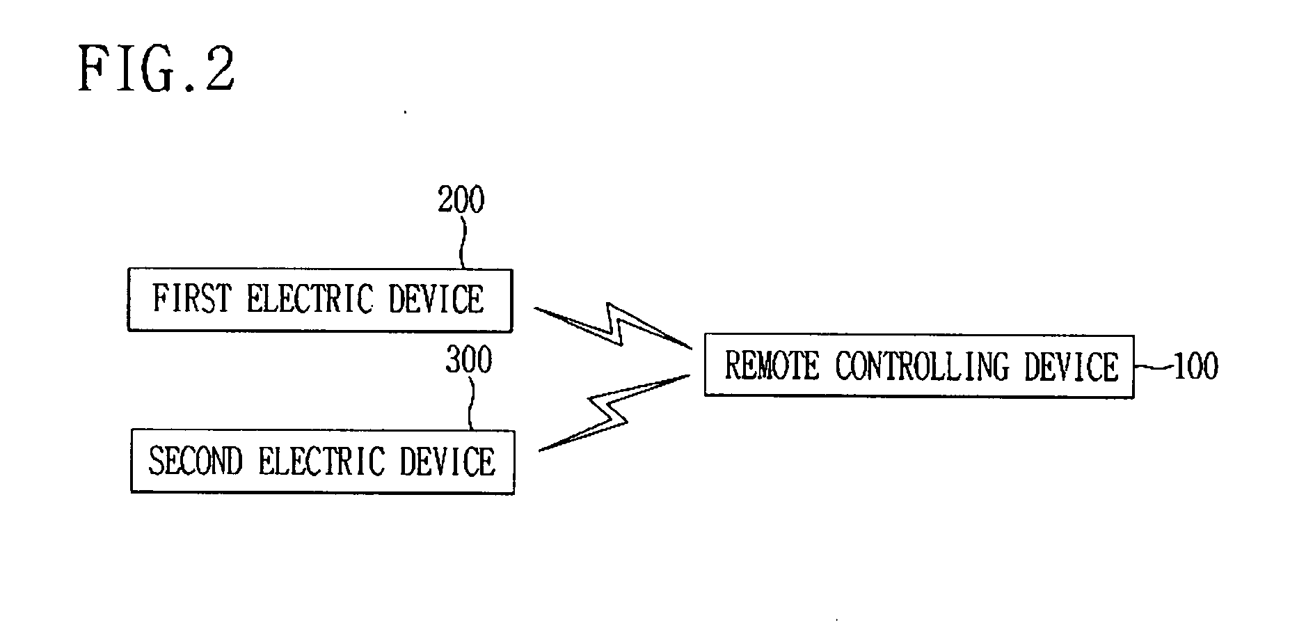
The present invention discloses a remote controlling system for an electric device which can control operations of electric devices such as a washer and a dryer and display states thereof. The remote controlling system for the electric device includes one or more electric devices for communicating with a remote controlling device through a wireless communication network, transmitting state information to the remote controlling device according to a state request command from the remote controlling device, and controlling a predetermined operation according to an operation control command from the remote controlling device, and the remote controlling device supplied with power by a common power source, for transmitting the state request command to the electric device selected by the user, receiving the state information from the electric device, and displaying the state information, or transmitting the operation control command to the electric device.

Description

TECHNICAL FIELD [0001] The present invention relates to a remote controlling system for an electric device, and more particularly, to a remote controlling system for an electric device which can control operations of electric devices such as a washer and a dryer and display states thereof. BACKGROUND ART [0002] In general, when the user puts dirty laundry into a wash tub, a washer washes the laundry by mixing a detergent and water, and rinses and dries the laundry. [0003] In addition, a clothes dryer dries the laundry by absorbing moisture from the laundry by sending hot air generated by a heater into a drum. [0004] The washer and the dryer are mostly installed indoors, but can be installed in a special space such as an outside warehouse or an underground washing room. [0005] Recently, researches have been actively made to do housework without temporal and spatial restrictions, by connecting home devices to an internet environment and remotely controlling operations of the home devi...

Claims


Application Information

Patent Timeline
Patent Type & Authority Applications(United States)
IPC IPC(8): G05B19/02
CPCG05B19/0423G05B2219/23051G05B2219/2633G05B2219/23297G05B2219/23178H04Q9/00H04Q2209/40
Inventor LEE, HOONBONGKIM, YONG-TAE
Owner LG ELECTRONICS INC
Why Eureka
Try Eureka