Exposure Apparatus and Device Manufacturing Method

a technology of exposure apparatus and manufacturing method, which is applied in the direction of photomechanical apparatus, instruments, printing, etc., can solve the problems of deterioration of exposure accuracy, insufficient focus margin during exposure operation, and insufficient holding of substrates by holders, so as to prevent the occurrence of disadvantages due to leaked liquid, good accuracy, and desired performance

Inactive Publication Date: 2008-02-21
NIKON CORP
View PDF16 Cites 59 Cited by
  • Summary
  • Abstract
  • Description
  • Claims
  • Application Information

AI Technical Summary

Benefits of technology

[0007] The present invention has been achieved in view of such circumstances, and has an object to provide an exposure apparatus that can prevent the occurrence of disadvantages due to leaked liquid, and to provide a device manufacturing method using the exposure apparatus.

Problems solved by technology

When the depth of focus δ becomes too narrow, it becomes difficult to make the substrate surface coincide with the image plane of the projection optical system, and thus there is the possibility that the focus margin during the exposure operation will be insufficient.
By the way, in an exposure apparatus utilizing the liquid immersion method, if the liquid flows from the upper surface of the substrate to the side of the back surface of the substrate and penetrates or inflows into the space between the substrate and the substrate holder that holds the substrate, there is a possibility that the substrate holder cannot hold the substrate sufficiently, leading to a disadvantage such as the deterioration of exposure accuracy.
Therefore, there occurs a disadvantage that a flatness (the degree of flatness) when the substrate is held by the substrate holder deteriorates, and thus good exposure accuracy cannot be maintained.

Method used


Image

  • Exposure Apparatus and Device Manufacturing Method
  • Exposure Apparatus and Device Manufacturing Method
  • Exposure Apparatus and Device Manufacturing Method

Examples


Embodiment Construction

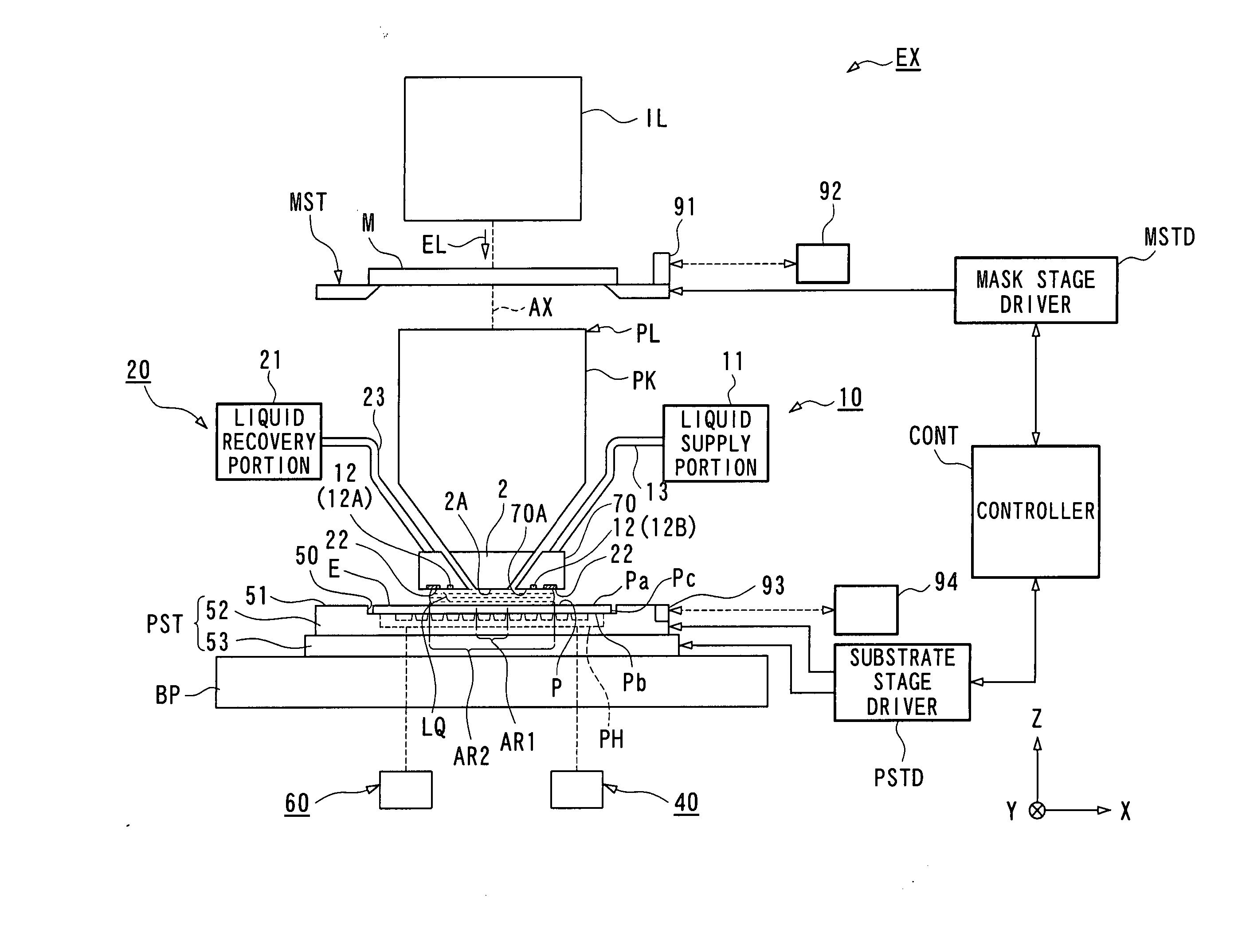
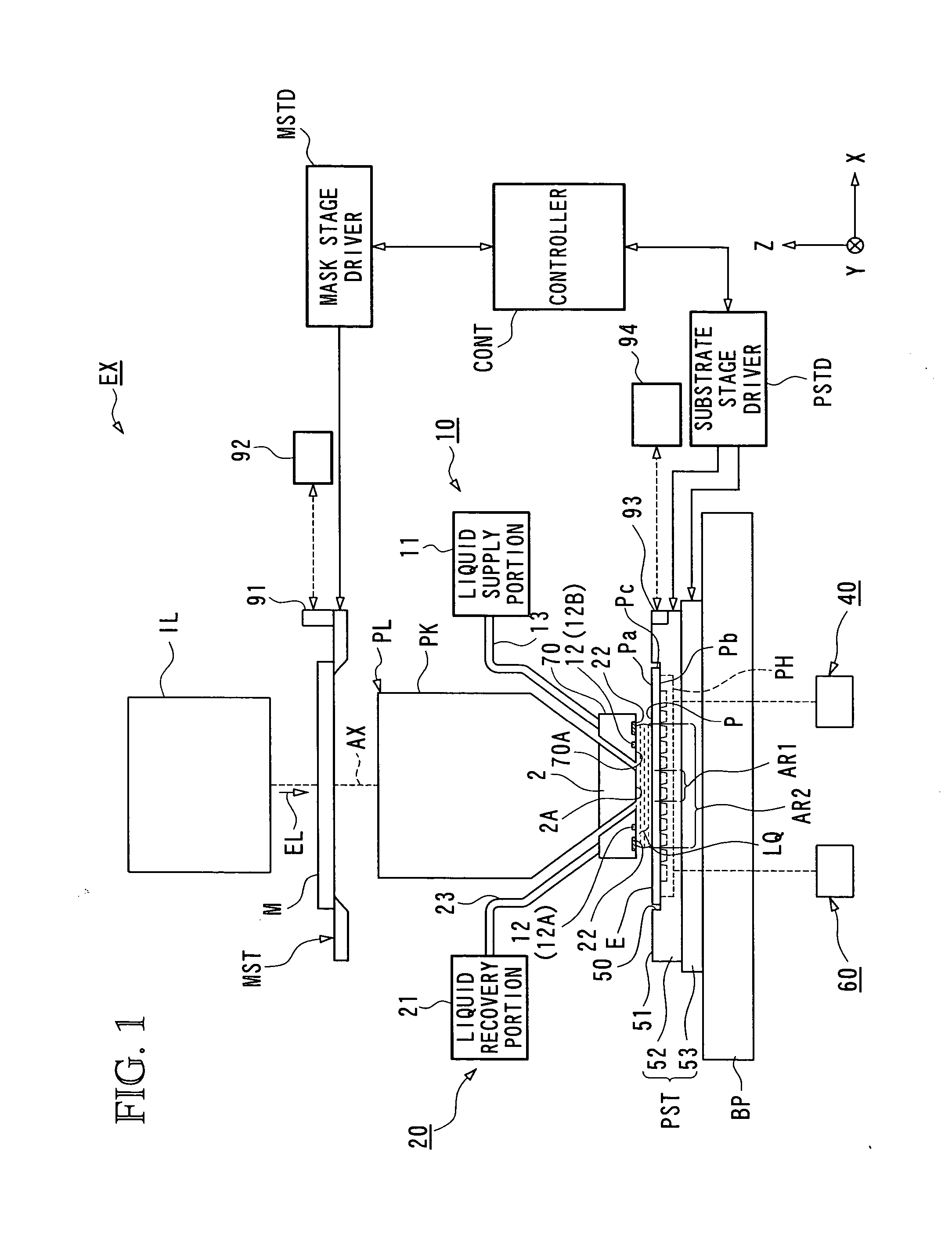
[0063] Hereunder is a description of embodiments of the present invention with reference to the drawings. FIG. 1 is a schematic block diagram showing an embodiment of an exposure apparatus of the present invention.

[0064] In FIG. 1, the exposure apparatus EX includes: a mask stage MST that is movable while supporting a mask M; a substrate stage PST that has a substrate holder PH for holding a back surface Pb of a substrate P and that is movable in the state with the substrate P being held by the substrate holder PH; an illumination optical system IL that illuminates the mask M supported by the mask stage MST with an exposure light EL; a projection optical system PL that projection-exposes a pattern image of the mask M illuminated with the exposure light EL onto a front surface Pa of the substrate P supported by the substrate stage PST; and a controller CONT that controls the overall operation of the exposure apparatus EX. Note that the term “substrate” referred to herein encompasses...


PUM

PropertyMeasurementUnit
wavelengthaaaaaaaaaa
refractive indexaaaaaaaaaa

Abstract

An exposure apparatus that can prevent disadvantages due to a leaked liquid is provided. The exposure apparatus includes: a substrate holder (PH) that includes a peripheral wall portion (33) and supporting portions (34) located on an inside of the peripheral wall portion (33) and that supports a substrate (P) with the supporting portions (34) by negatively pressurizing a space (31) surrounded by the peripheral wall portion (33); and a recovery mechanism that includes a collection inlets (61) provided on the inside of the peripheral wall portion (33) and a vacuum system (63) connected to the collection inlets (61), in which a liquid penetrated from an outer periphery of the substrate (P) is sucked and recovered, in the state with an upper surface (33A) of the peripheral wall portion (33) and a back surface (Pb) of the substrate (P) being spaced at a first distance.

Description

TECHNICAL FIELD [0001] The present invention relates to an exposure apparatus that exposes a substrate via a liquid and to a device manufacturing method. [0002] Priority is claimed on Japanese Patent Application No. 2004-182678, filed on Jun. 21, 2004, the content of which is incorporated herein by reference. BACKGROUND ART [0003] Semiconductor devices and liquid crystal display devices are manufactured through the so-called photolithography technique, by which a pattern formed on a mask is transferred onto a photosensitive substrate. The exposure apparatus used in the photolithography process has a mask stage that supports a mask and a substrate stage that supports a substrate via a substrate holder, and while successively moving the mask stage and the substrate stage, transfers the mask pattern, via a projection optical system, onto the substrate. In recent years, there has been demand for higher resolution projection optical systems in order to handle the much higher levels of in...

Claims


Application Information

Patent Timeline
Patent Type & Authority Applications(United States)
IPC IPC(8): G03B27/42G03F7/20H01L21/027
CPCG03F7/2041G03F7/70866G03F7/707G03F7/70341H01L21/683H01L21/0274G03F7/70716
Inventor SHIBUTA, MAKOTO
Owner NIKON CORP
Why Eureka
Try Eureka