Three-Dimensional Thermal Spreading in an Air-Cooled Thermal Device

a three-dimensional thermal spread and air-cooled technology, applied in the direction of indirect heat exchangers, electrical apparatus construction details, lighting and heating apparatuses, etc., can solve the problems of reducing the efficiency or effectiveness of the electronic component, affecting the cooling effect of the air-cooled device, and damage to the electronic componen

Active Publication Date: 2008-02-21
ATI TECH INC
View PDF41 Cites 27 Cited by
  • Summary
  • Abstract
  • Description
  • Claims
  • Application Information

AI Technical Summary

Problems solved by technology

These assemblies are often confined within casings where convective air cooling is hampered.
Cooling solutions are necessary for certain electronic components to maintain operational temperatures below a critical level, which, if reached, may damage the electronic component or reduce its efficiency or effectiveness.
Known conductive and convective air-cooling methods, however, fail to provide adequate heat removal for certain electronic devices that use intensive heat generating components or require intense local cooling.
The surface of components may also heat unevenly, creating hot spots that, unless cooled locally, reduce the overall efficiency of the thermal management device by reducing the average temperature difference between the component surface and the device before the component surface temperature reaches a critical level.
Improved efficiency of new thermal management devices for small heating components used in electronic devices is limited where the internal space between the various components is of known and recognized usefulness.
These cooling methods from the prior art, if used individually, can fail to address one or more of the problems of increased heat fluxes, limited encumbrance, limited convective air flow, reduced heating surfaces, and colder junction temperatures requirements.

Method used


Image

  • Three-Dimensional Thermal Spreading in an Air-Cooled Thermal Device
  • Three-Dimensional Thermal Spreading in an Air-Cooled Thermal Device
  • Three-Dimensional Thermal Spreading in an Air-Cooled Thermal Device

Examples


Embodiment Construction

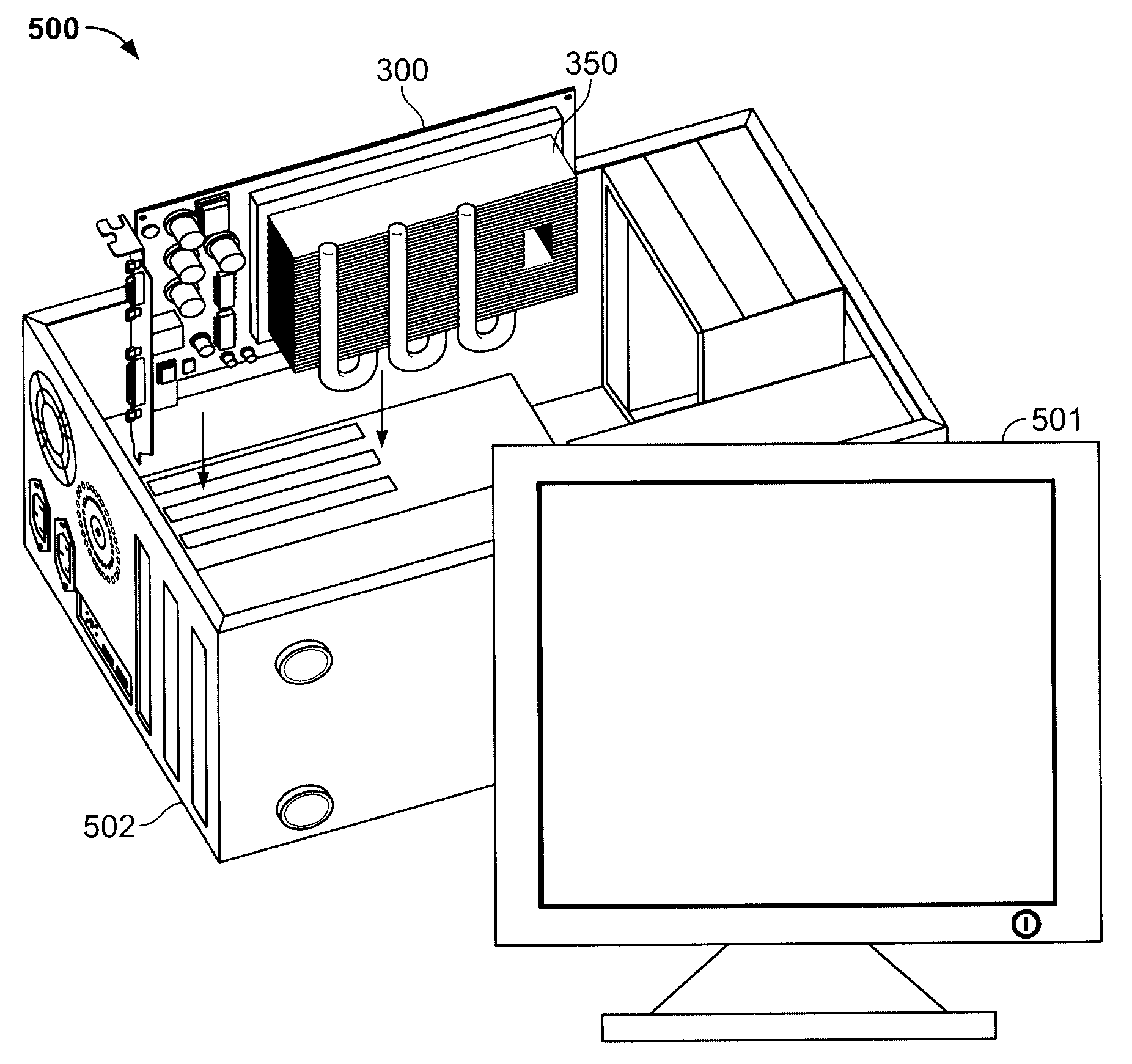
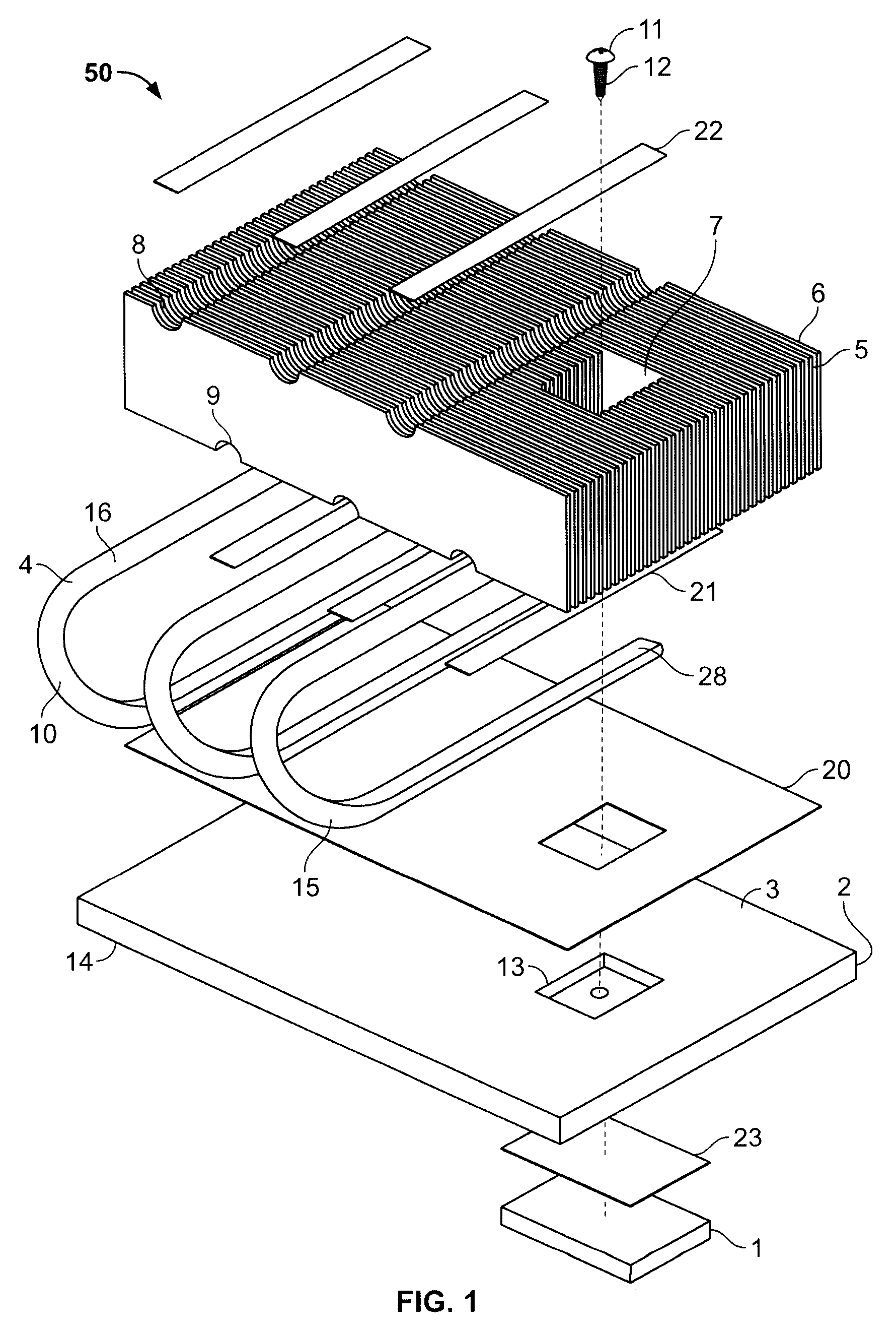
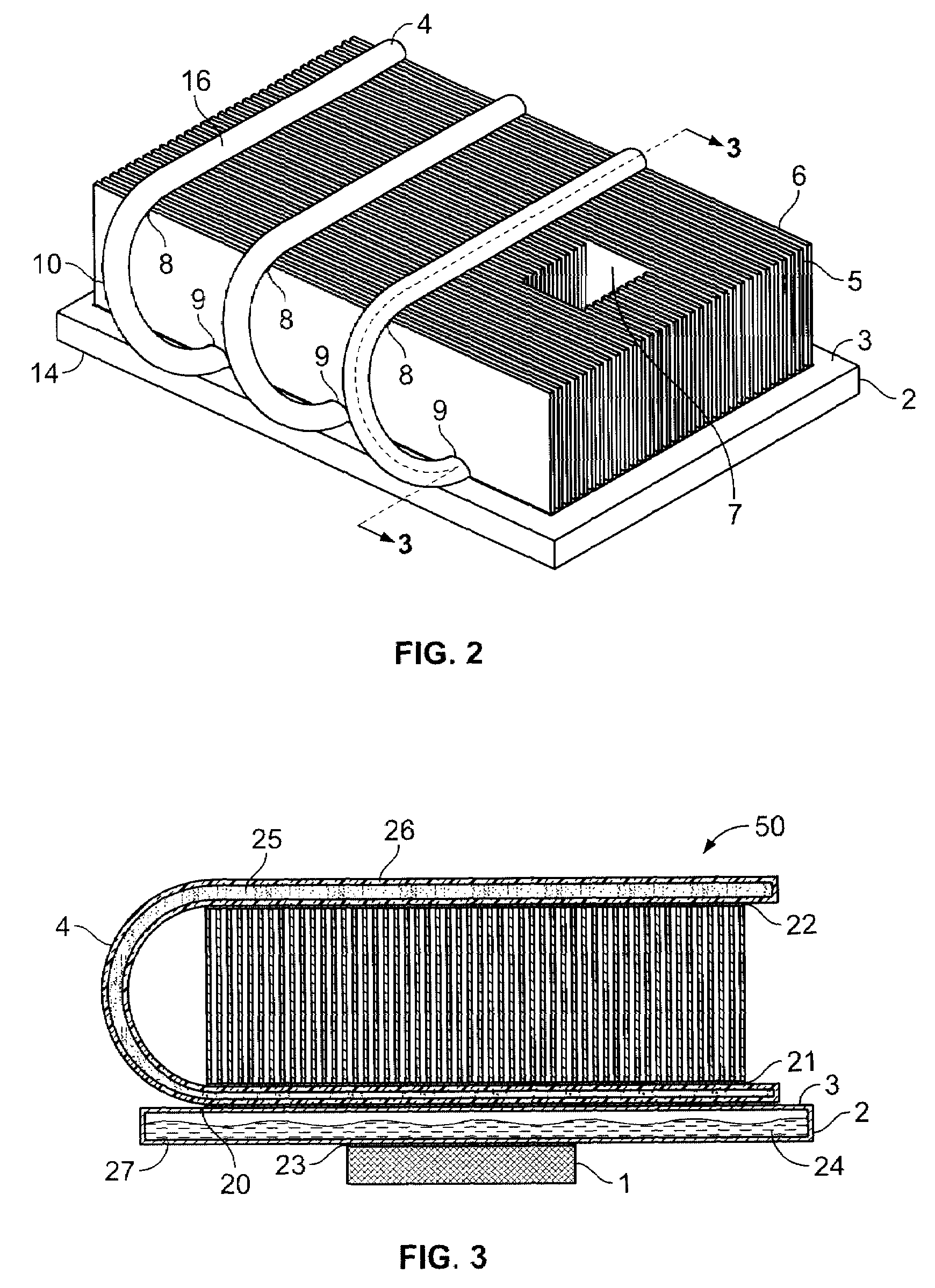
[0019]In the following detailed description, reference is made to the accompanying drawings that show, by way of illustration, several embodiments of the disclosure, each centered around an improved thermal management device based on vapor chamber technology. These embodiments are described with sufficient detail to enable one skilled in the art to practice the disclosure. It is understood that the various embodiments of the disclosure, although different, are not necessarily exclusive and can be combined differently because they show novel features. For example, a particular feature, structure, heat dissipation vehicle, or characteristic described in connection with one embodiment may be implemented within other embodiments without departing from the spirit and scope of the disclosure. In addition, it is understood that the location and arrangement of individual elements, such as geometrical parameters, within each disclosed embodiment may be modified without departing from the spi...


PUM


Abstract

The present disclosure relates to heat transfer thermal management device utilizing varied methods of heat transfer to cool a heat generating component from a circuit assembly or any other embodiment where a heat generating component can be functionally and operatively coupled. In a proposed embodiment, at least one heat pipe is used to transfer heat from the condensation portion of a vapor chamber to cool a bottom portion of a finned heat dissipation space and transfer the heat to a colder location on the heat fins. In another proposed embodiment, the water vapor chamber is placed in a heat sink and is adapted to thermally connect to at least one heat pipe.

Description

FIELD OF THE INVENTION[0001]The present invention generally relates to thermal management of electronic components, and more particularly, to thermal management devices that employ liquid chambers.BACKGROUND OF THE INVENTION[0002]Electronic components such as integrated circuit chips produce heat during operation. These components may be mounted on circuit substrates to form circuit assemblies. These assemblies are often confined within casings where convective air cooling is hampered. Cooling solutions are necessary for certain electronic components to maintain operational temperatures below a critical level, which, if reached, may damage the electronic component or reduce its efficiency or effectiveness. Thermal management devices are mounted to the electronic component to be cooled and drain heat from the component by heat conduction, heat convection or heat irradiation. Ultimately, the heat from the component is drained to the surrounding air in a forced or natural flow of air. ...

Claims


Application Information

Patent Timeline
Patent Type & Authority Applications(United States)
IPC IPC(8): H05K7/20
CPCF28D15/0266H01L23/427H01L2924/3011F28F2215/06F28D15/0233H01L2924/0002F28D15/0275H01L2924/00
Inventor REFAI-AHMED, GAMAL
Owner ATI TECH INC
Why Eureka
Try Eureka