
Method and apparatus for cooperative multithreading

a multi-threading and cooperative technology, applied in the field of multi-threading processing, can solve the problems of low utilization of functional units, high design complexity, power consumption and overhead of multi-threading, etc., and achieves the effect of reducing the number of dsp applications

Inactive Publication Date: 2008-02-21
CHEN TIEN FU
View PDF8 Cites 52 Cited by
  • Summary
  • Abstract
  • Description
  • Claims
  • Application Information

AI Technical Summary

Benefits of technology

[0014]It is still another asepct of the present invention to provide a flexible interface for integrating the required functionality (for example, audio and video data types processing).

Problems solved by technology

However, the instruction-level parallelism is not sufficient because of data dependencies, which result in low the utilization of functional units.
However, for embedded processors, a superscalar processor with multithreading has the overhead of power consumption and high design complexity, such that it is unacceptable for Digital Signal Processing (DSP) applications with power and size requirements.
VLIW processors with multithreading impose several problems with fetching VLIW instructions from multiple threads.
In the VLIW architecture, fixed fetch bandwidth results in fetching only one VLIW instruction from one thread, such that thread switching timing is critical on cache miss, branch miss prediction, etc.
For rapid algorithm developments and architectural variations, conventional Application Specific Integrated Circuit (ASIC) designs take longer to develop and cannot meet rapid variation in both algorithms and specifications.
Although shrink feature size makes more transistors per square millimeter, which enables larger memory systems to be integrated on a chip, high code density still dominates performance bottlenecks due to the gap between the processor and memory system.

Method used


Image

  • Method and apparatus for cooperative multithreading
  • Method and apparatus for cooperative multithreading
  • Method and apparatus for cooperative multithreading

Examples


Embodiment Construction

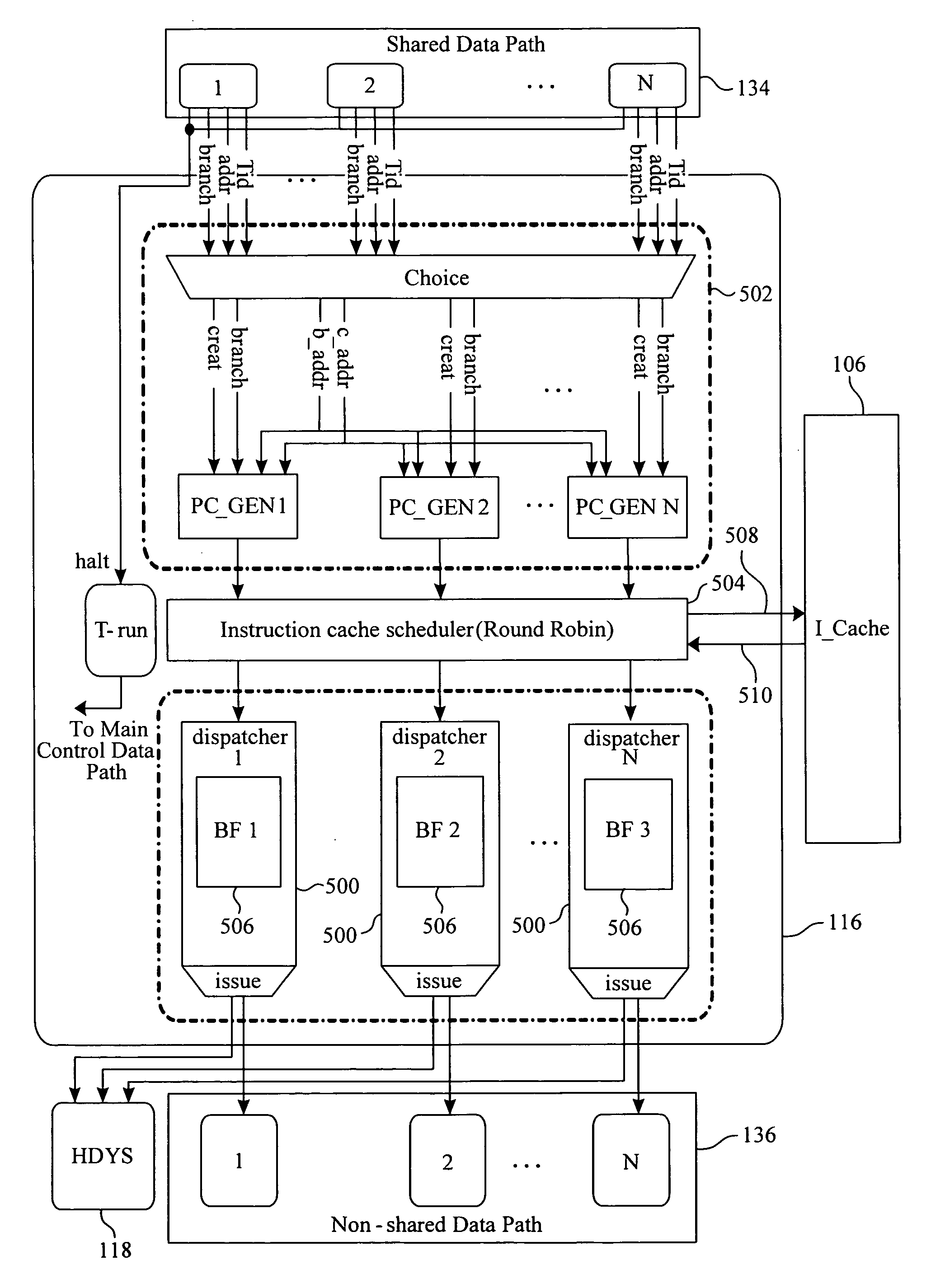
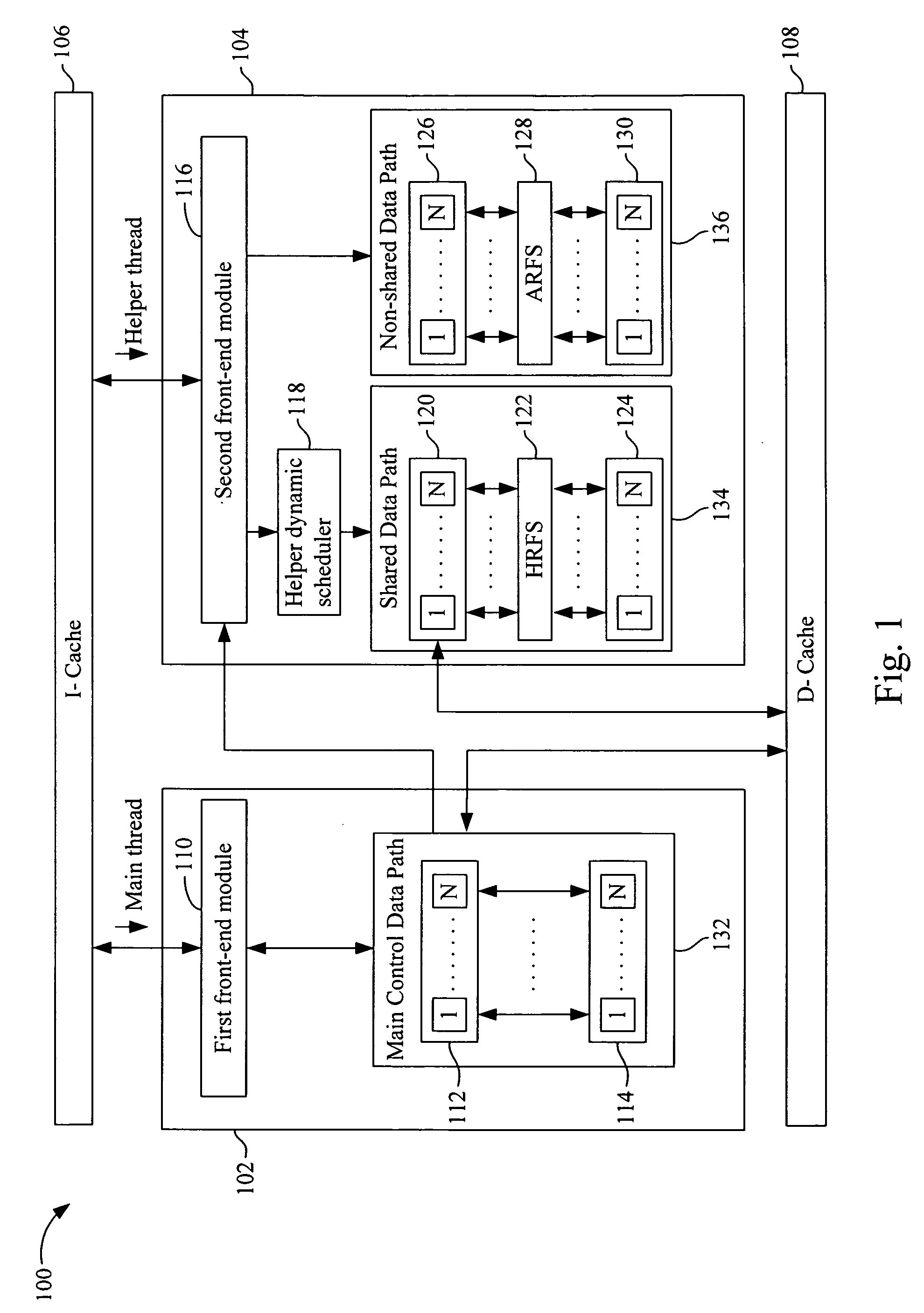
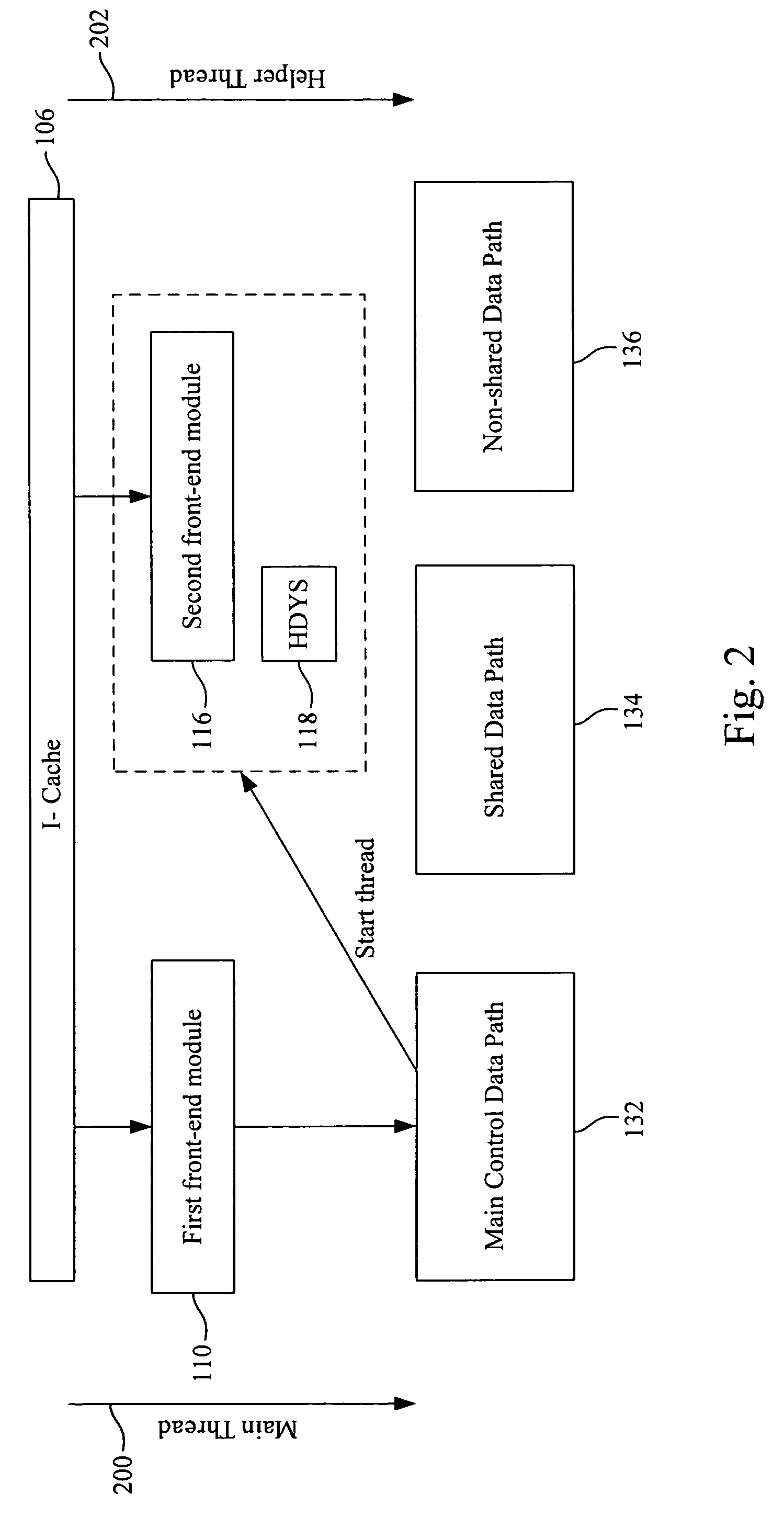
[0033]FIG. 1 is a schematic diagram of a cooperative multithreading architecture 100 with which the present invention may be implemented. The cooperative multithreading architecture 100 includes a first cluster 102 and a second cluster 104, wherein a main thread goes through the first cluster 102 and a helper thread goes through the second cluster 104.

[0034]The first cluster 102 is capable of controlling and carrying out routine computations. The first cluster 102 includes a first front-end module 110 and a main control data path 132, wherein the main control data path 132 includes a plurality of functional units 112 and a plurality of register files 114. The first front-end module 110 may use Reduced Instruction Set Computing (RISC) operations for branch, load, store, arithmetic and logical operations, etc. The operations for functional units 112 are multiply-and-add or Single Instruction Multiple Data (SIMD), etc. Moreover, the first cluster 102 takes charge of creating a helper t...


PUM


Abstract

A cooperative multithreading architecture includes an instruction cache, capable of providing a micro-VLIW instruction; a first cluster, connects to the instruction cache to fetch the micro-VLIW instruction; and a second cluster, connects to the instruction cache to fetch the micro-VLIW instruction and capable of execution acceleration. The second cluster includes a second front-end module, connects to the instruction cache and capable of requesting and dispatching the micro-VLIW instruction; a helper dynamic scheduler, connects to the second front-end module and capable of dispatching the micro-VLIW instruction; a non-shared data path, connects to the second front-end module and capable of providing a wider data path; and a shared data path, connected to the helper dynamic scheduler and capable of assisting a control part of the non-shared data path. The first cluster and the second cluster carry out execution of the respective micro-instructions in parallel.

Description

BACKGROUND[0001]1. Field of Invention[0002]The present invention relates generally to multithreaded processing. More particularly, the present invention relates to a method and apparatus for a cooperative multithreading.[0003]2. Description of Related Art[0004]Increasingly growth of processing power drives the inclusion of central processing units with digital signal processors for multimedia applications. As such, these processors with multiple instruction pipelines allow parallel processing of multiple instructions. However, the instruction-level parallelism is not sufficient because of data dependencies, which result in low the utilization of functional units. Therefore, thread-level parallelism is used to execute multiple threads concurrently to increase the utilization of functional units.[0005]Superscalar processors with multithreading explored by Intel use dynamic thread creation and a detection circuitry to detect speculation errors in the execution of the threads. However, ...

Claims


Application Information

Patent Timeline
IPC IPC(8): G06F15/00
CPCG06F9/3012G06F9/3851G06F9/3802G06F9/30123G06F9/3888
Inventor CHEN, TIEN-FUCHOU, SHU-HSUANCHENG, CHIEH-JENKANG, ZHI-HENG
Owner CHEN TIEN FU
Learn More