Signal conditioning apparatus and method for determination of permanent magnet motor rotor position

a technology of signal conditioning apparatus and permanent magnet motor, which is applied in the direction of motor/generator/converter stopper, dynamo-electric converter control, dynamo-electric gear control, etc., can solve the problem that back emf-based sensorless control methods cannot sustain low and zero speed operations

Active Publication Date: 2008-02-28
INFINEON TECH AMERICAS CORP
View PDF8 Cites 21 Cited by
  • Summary
  • Abstract
  • Description
  • Claims
  • Application Information

AI Technical Summary

Benefits of technology

[0008] Accordingly, the disclosed embodiment of the invention provides a method and system including a simple signal conditioning unit and method to extract rotor angle information from mo

Problems solved by technology

Back EMF-based sensorless control methods c

Method used


Image

  • Signal conditioning apparatus and method for determination of permanent magnet motor rotor position
  • Signal conditioning apparatus and method for determination of permanent magnet motor rotor position
  • Signal conditioning apparatus and method for determination of permanent magnet motor rotor position

Examples


Embodiment Construction

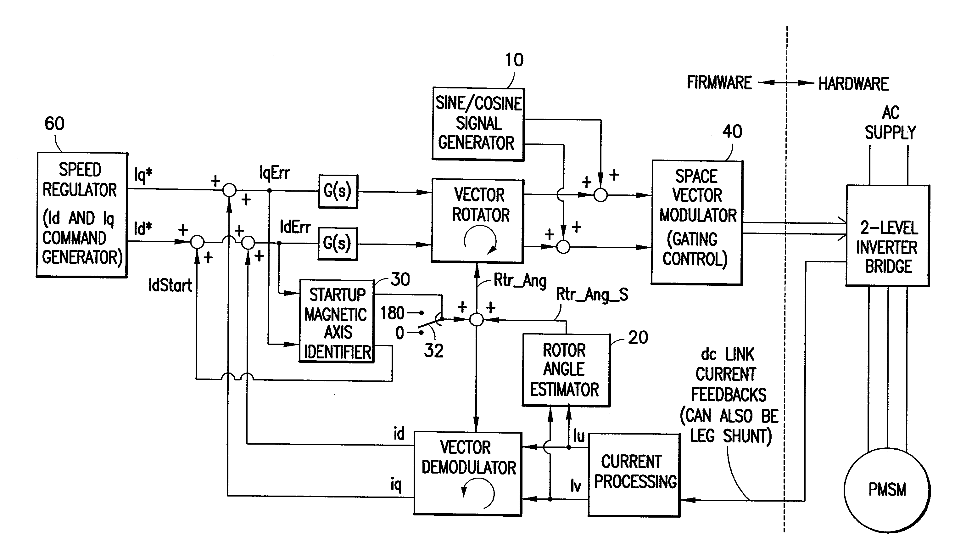
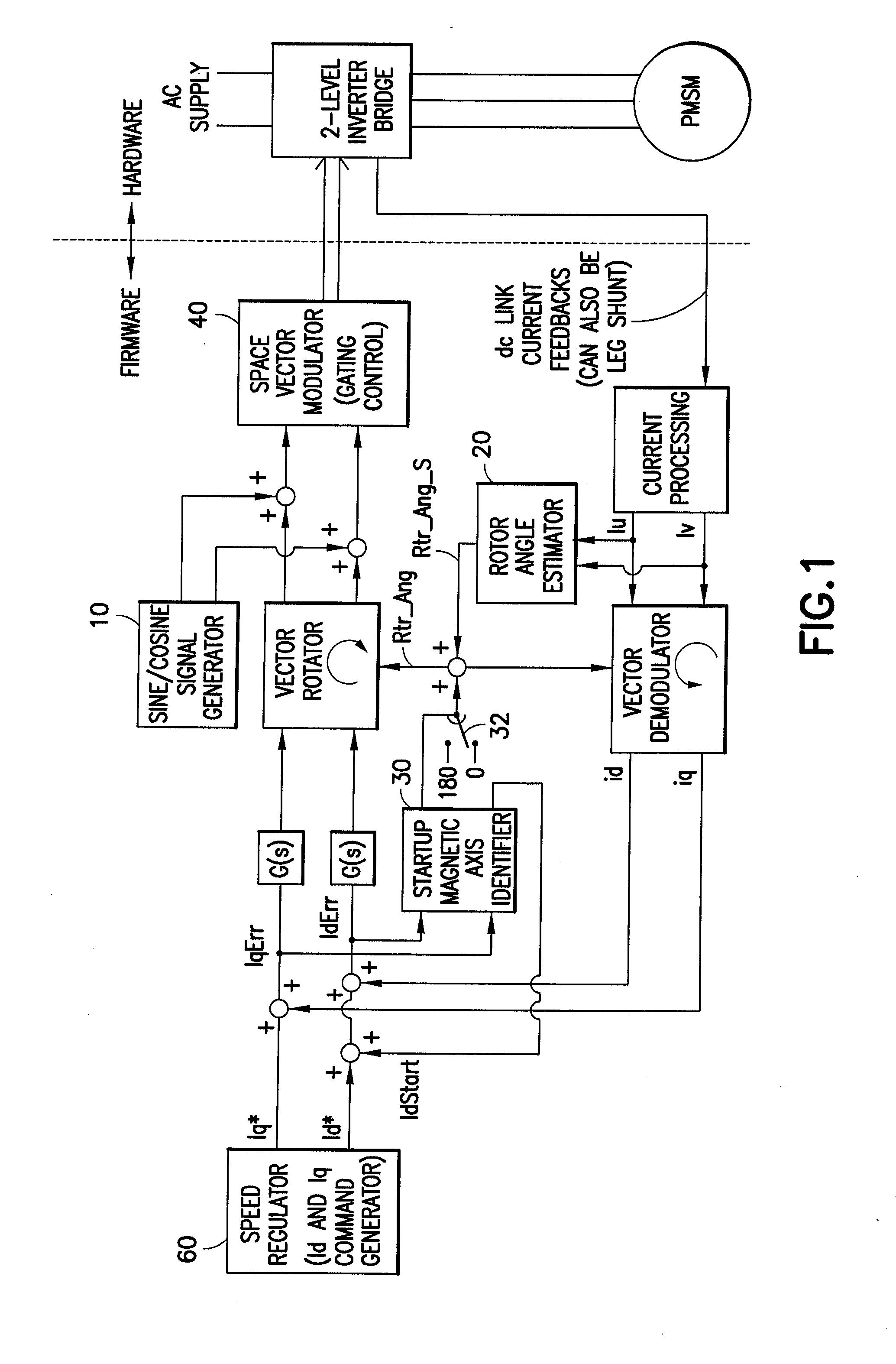
[0033] The present invention relates to a motor control technique. The technique may advantageously be implemented in firmware, but the invention is not limited to the disclosed implementation.

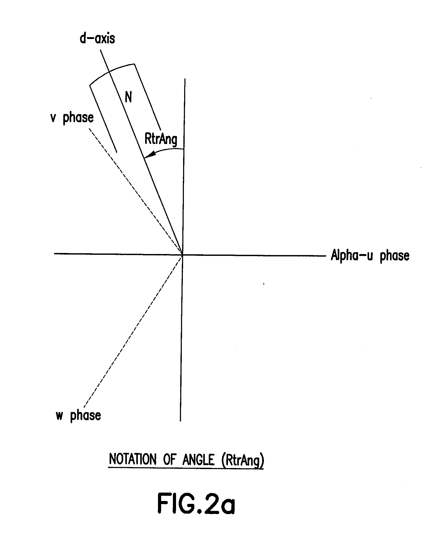
[0034] A block diagram of the control technique is shown in FIG. 1. The d-axis is the orientation that aligns with the magnetic axis of the rotor (which is the convention in most published articles). The shaded boxes (sine / cosine signal generator 10, signal conditioning unit for rotor magnetic axis angle estimation 20, startup magnetic axis polarity identifier 30) are the major components of rotor angle estimation. The sine / cosine signal generator 10 outputs high frequency sine and cosine signals that are superimposed into the input of the space vector modulator 40. This in effect imposes a high frequency component on the current waveform. The signal-conditioning unit 20 extracts rotor magnetic axis information from the feedback currents (Iu and Iv). The signal conditioning unit tracks magnet...


PUM


Abstract

An apparatus and method for estimating rotor angle information for the control of permanent magnet AC motors having sinusoidal current excitation. The disclosed motor drive can provide full load operation at very low speeds including zero speed without the use of a shaft position sensing device. The rotor angle is estimated through injection of high frequency current, and rotor angle is extracted by a signal-conditioning algorithm, which utilizes current amplitude differential to discriminate the rotor angle. Rotor angle magnetic axis orientation (North or South pole) at startup is detected by comparing time average current ripple (at signal injection frequency) content between two different levels of d-axis current injection.

Description

CROSS-REFERENCE TO RELATED APPLICATIONS [0001] This application is based upon and claims priority of U.S. Provisional Ser. No. 60 / 807,241 filed Jul. 13, 2006, by Eddy Ying Yin HO, titled SIGNAL CONDITIONING APPARATUS FOR DETERMINATION OF PERMANENT MAGNET MOTOR ROTOR POSITION (IR-3239 PROV (2-5260)), incorporated by reference.BACKGROUND OF THE INVENTION [0002] 1. Field of the Invention [0003] The present invention relates to a signal conditioning apparatus and method for determination of permanent magnet motor rotor position. [0004] 2. Related Art [0005] Rotor position information is in general required for stable operation of permanent magnet AC motors. Continuous rotor position can be obtained from an encoder mounted on a motor shaft or obtained indirectly through estimation algorithms (based on voltage and current feedbacks). The latter is preferred for lower system and operating cost. [0006] Back EMF-based sensorless control methods cannot sustain low and zero speed operations. A...

Claims


Application Information

Patent Timeline
IPC IPC(8): H02P21/14
CPCH02P6/185
Inventor HO, EDDY YING YIN
Owner INFINEON TECH AMERICAS CORP
Why Eureka
Try Eureka