

Magnetic Rotation-Angle Sensor and Angle-Information Processing Device
a technology of rotation angle sensor and angle information processing, which is applied in the direction of measurement device, instrument, using electrical means, etc., can solve the problems of low angular resolution in the rotation angle of the magnet, increased number of magnetic poles, and complicated circuit configuration for signal processing, etc., to achieve flexibility in design
- Summary
- Abstract
- Description
- Claims
- Application Information
AI Technical Summary
Benefits of technology
Problems solved by technology
Method used
Image

Examples
embodiment 1
[0062] A first embodiment of the present invention will be described with reference to FIGS. 1 to 6.
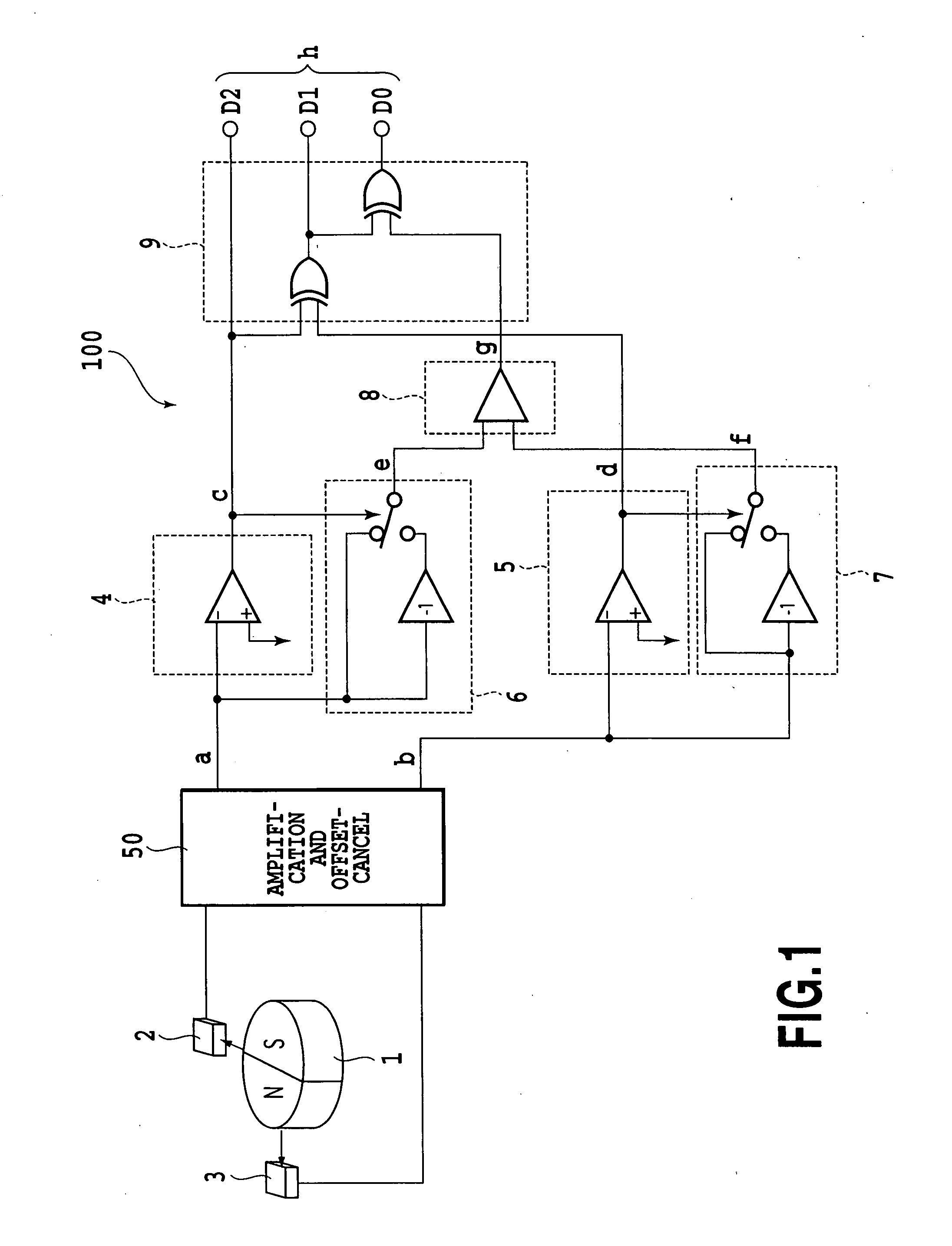
[0063]FIG. 1 is a diagram showing the circuit configuration of a magnetic rotation-angle sensor 100 according to the present invention.
[0064] The sensor is configured with a magnet 1 having a pair of an N-polarity magnetic pole and an S-polarity magnetic pole, magnetic sensors 2 and 3, an amplification and offset-cancel circuit 50, polarity determination circuits 4 and 5, absolute-value generation circuits 6 and 7, a comparison circuit 8, and an angle determination circuit 9. In addition, the amplification and offset-cancel circuit 50 is not a necessitated structure element.
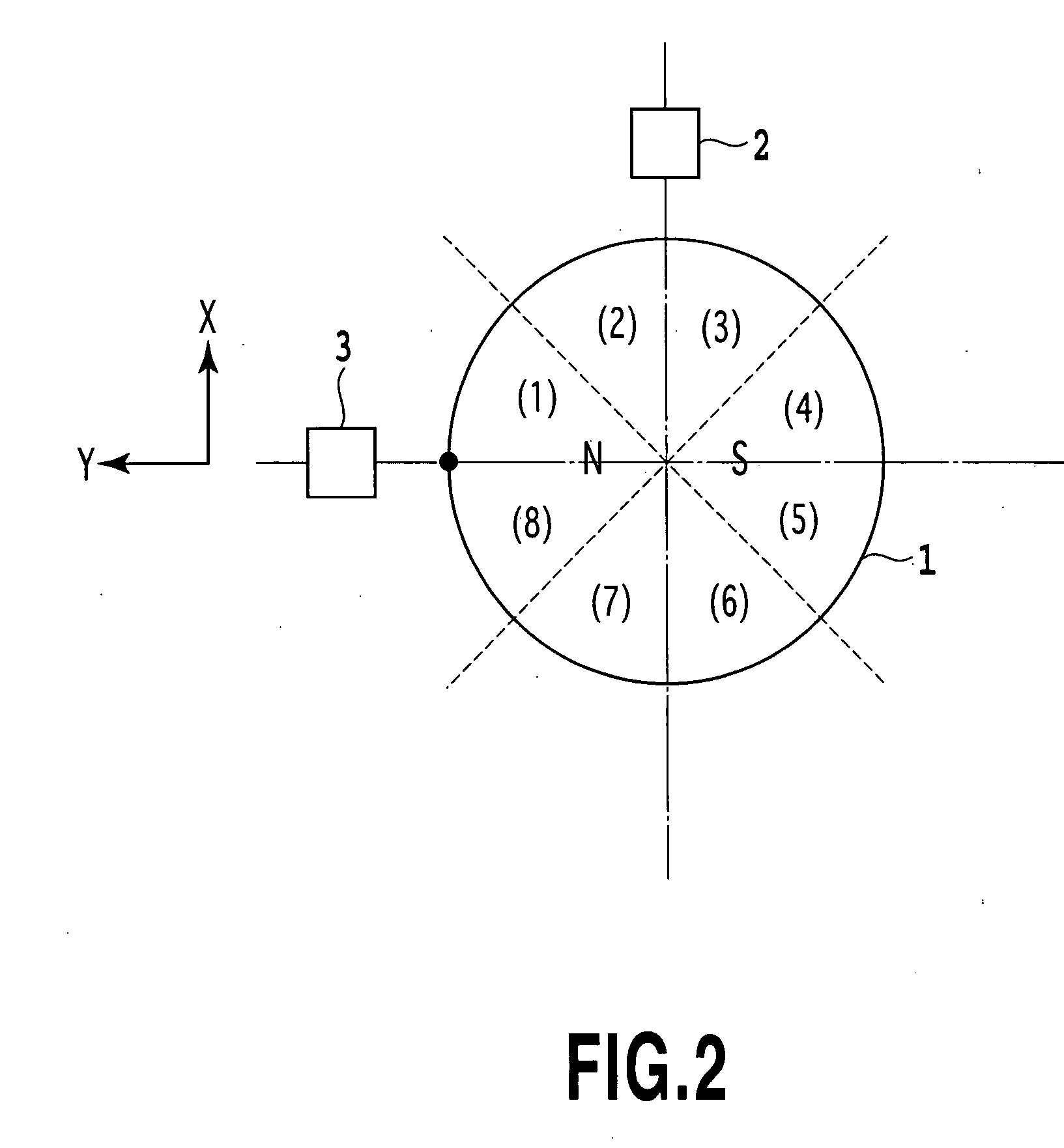
[0065] The magnetic sensors 2 and 3 are arranged around the magnet 1. The magnetic sensor 2 is spaced apart from the magnetic sensors 3 by an angle of 90° to the rotation center of the magnet 1.
[0066] The polarity determination circuits 4 and 5 determine the polarities of sensor output signals a and b outputted...
embodiment 2
[0096] A second embodiment of the present invention will be described with reference to FIGS. 7 to 10. The same reference numerals are applied to the parts corresponding to the first example and an explanation thereof is omitted.
[0097]FIG. 7 is a diagram showing the circuit configuration of a magnetic rotation-angle sensor 110 according to the present invention.
[0098] The sensor is configured with a magnet 1 having a pair of an N-polarity magnetic pole and an S-polarity magnetic pole, three magnetic sensors 2, 3 and 10, an amplification and offset-cancel circuit 50, polarity determination circuits 4, 5, and 11, absolute-value generation circuits 6, 7 and 11, comparison circuits 8, 13, and 14, and an angle determination circuit 15. In addition, the amplification and offset-cancel circuit 50 is not necessarily required to be provided.
[0099] The magnetic sensors 2 and 3 are arranged around the magnet 1. The magnetic sensor 2 is spaced apart from the magnetic sensor 3, by a predeterm...
embodiment 3
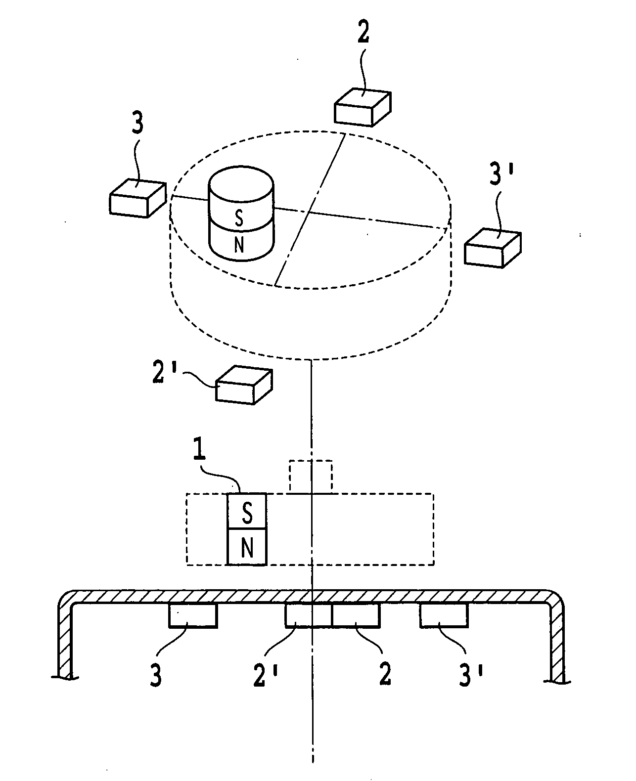
[0131] A third embodiment of the present invention will be described with reference to FIGS. 11 and 12. The same reference numerals are applied to the parts corresponding to the above described embodiments and an explanation thereof is omitted.
[0132] The third example is an example of a pair of magnetic sensors, such as the magnetic rotation-angle sensors 100 of FIG. 1 or the magnetic rotation-angle sensors 110 of FIG. 7 that are arranged around the magnet 1.
[0133]FIG. 11 shows a pair of the magnetic sensors 2 and 3 of FIG. 1 according to the first example. in Embodiment 1 described above are configured as respective pairs.
[0134] A pair of the magnetic sensor 2 and a magnetic sensor 2′ is arranged at a diagonal line X that passes through the rotation center of the magnet 1. Similarly, a pair of magnetic sensor 3 and a magnetic sensor 3′ is arranged at a diagonal line Y.
[0135] As described above, in the case that two pairs of magnetic sensors are arranged and differences accordin...
PUM
 Abstract
Description
Claims
Application Information