
Medium Voltage or High Voltage Audio Power Amplifier and Protection Circuit

a protection circuit and high-voltage technology, applied in the direction of amplifiers with semiconductor devices only, differential amplifiers, amplifiers with semiconductor devices/discharge tubes, etc., can solve the problems of slow operating speed of fuses and rarely protecting modem high-power amplifiers, and achieve fast and reliable protection, the effect of slow operating speed

Inactive Publication Date: 2008-02-28
SHIH KELVIN
View PDF3 Cites 12 Cited by
  • Summary
  • Abstract
  • Description
  • Claims
  • Application Information

AI Technical Summary

Benefits of technology

[0007] Fuses have a slow operating speed and rarely protect modem high power amplifiers. The present invention also describes a fast and reliable protection circuit that will instantaneously turn off the amplifier when a certain load current is exceeded. The circuit can protect both the power amplifier and the loud speakers.
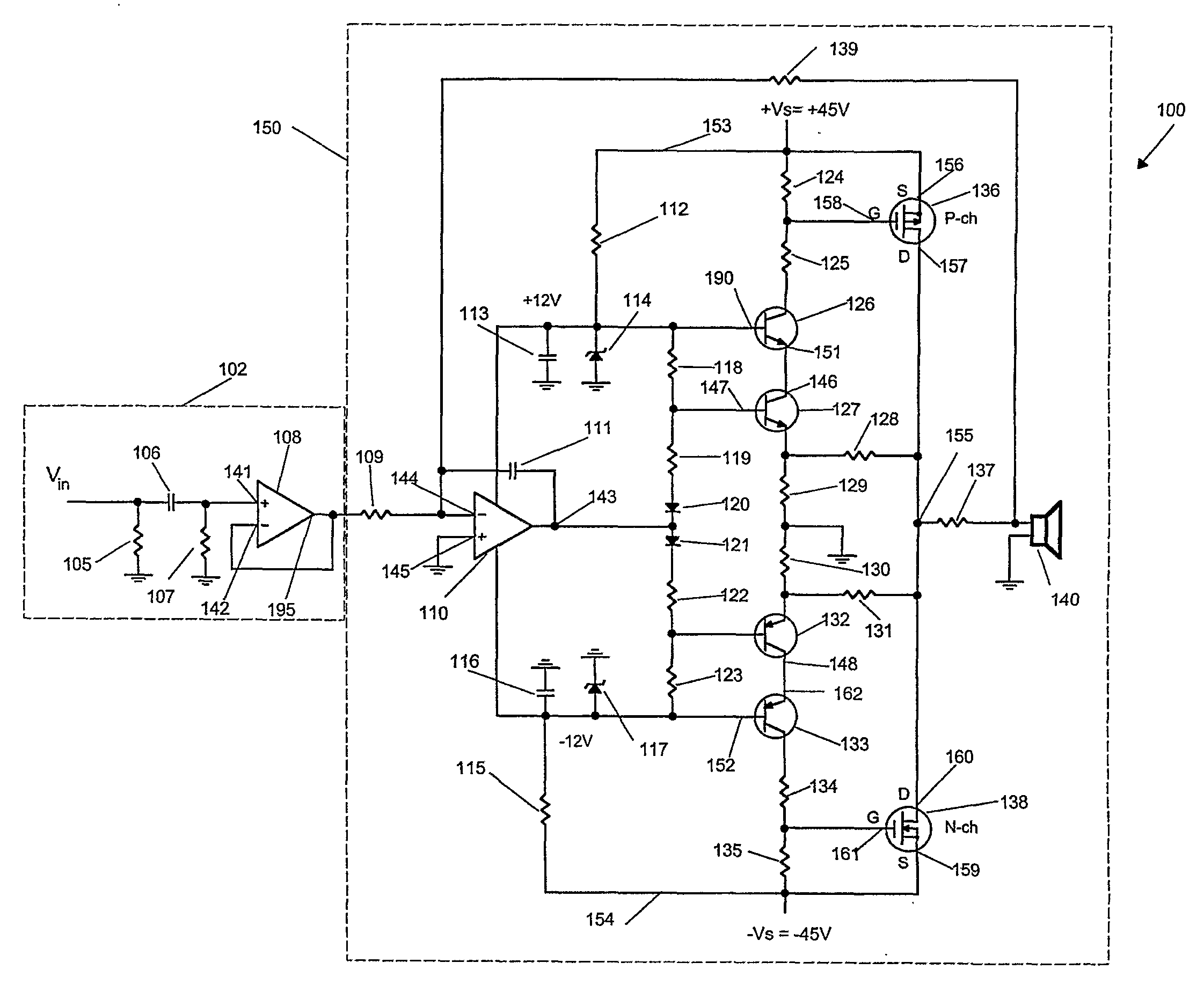
[0008] A sampling resistor located between the speaker and the output of the power amplifier measures the current. Since a negative feedback loop is closed around the sampling resistor, it will not cause any negative effect on the performance of the power amplifier. The sampling resistor is inside the negative feedback loop so that the output resistance of the power amplifier will be zero. A feedback resistor and an input resistor determine the gain of the power amplifier. High open loop gain of the operational amplifier provides the linearity and fidelity to the power amplifier. A complementary common-source MOSFET output stage provides current, voltage and power gain. Combine the two, and a fast, powerful and accurate power amplifier can be easily built.

Problems solved by technology

Fuses have a slow operating speed and rarely protect modem high power amplifiers.

Method used


Image

  • Medium Voltage or High Voltage Audio Power Amplifier and Protection Circuit
  • Medium Voltage or High Voltage Audio Power Amplifier and Protection Circuit
  • Medium Voltage or High Voltage Audio Power Amplifier and Protection Circuit

Examples


Embodiment Construction

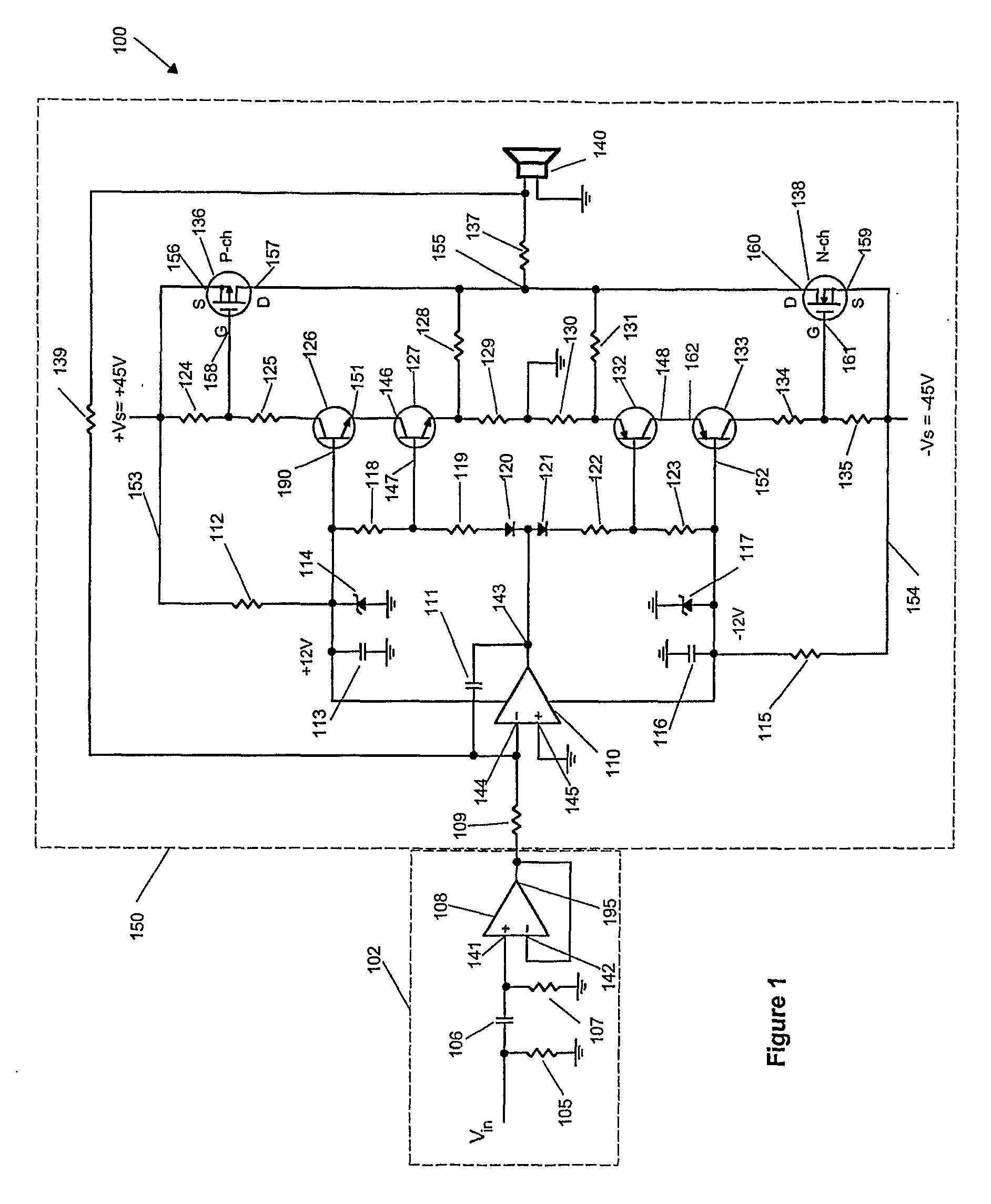
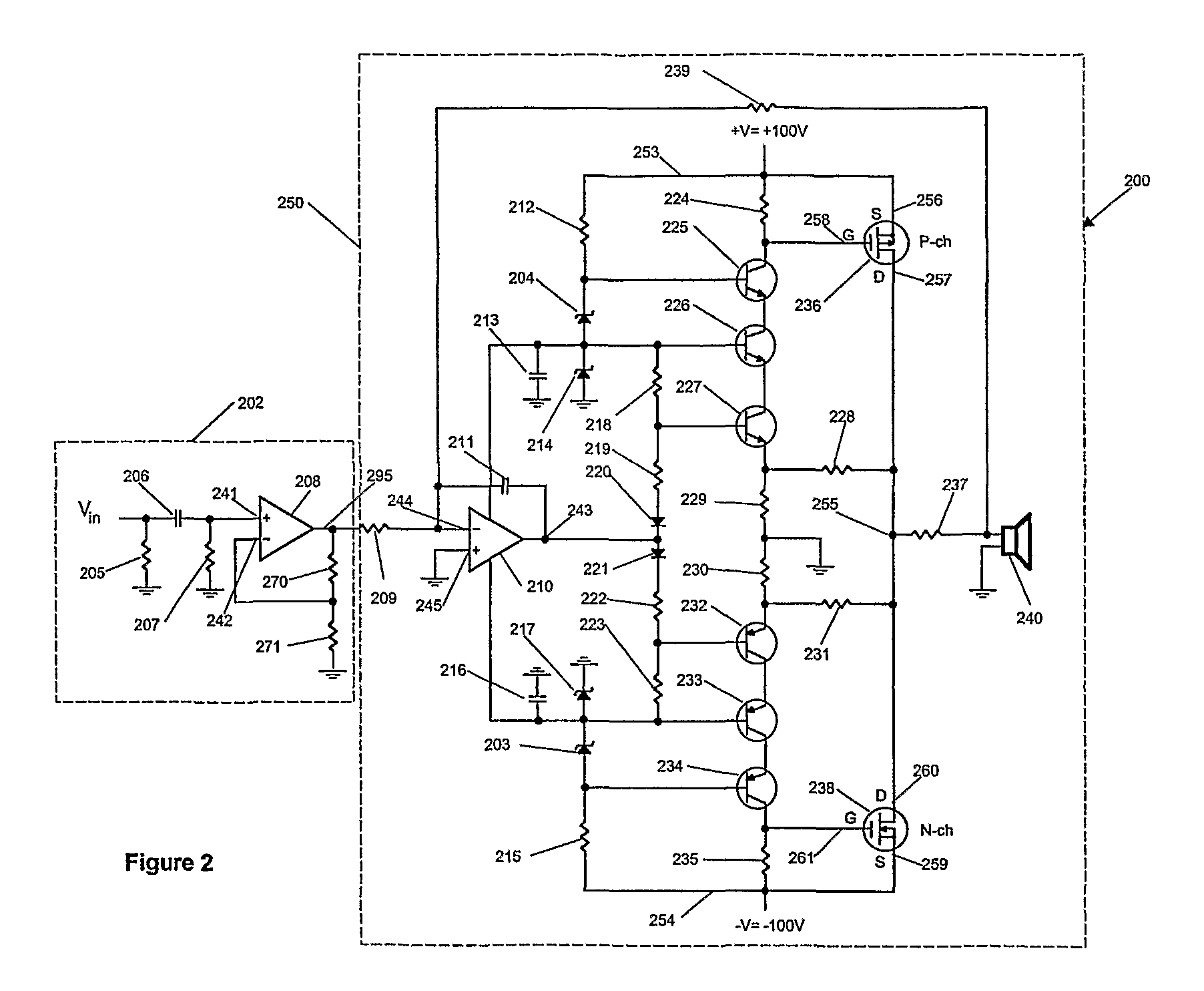
[0020]FIG. 1 illustrates a circuit 100 for a medium voltage power amplifier. The circuit 100 includes an output terminal 155, which drives a speaker 140 through a sampling resistor 137. The circuit 100 can be connected to any music source provided the output voltage is compatible to the input of the power amplifier. For example, a computer head phone jack, a portable CD player, a DVD player, a VCD, a MP3 player, or a TV sound output can all be used to drive the power amplifier.

[0021] An input amplifier 102 eliminates a direct current component of a music signal before it enters a power amplifier stage 150 and still maintains its low frequency response. An input voltage Vin enters a circuit including resistors 105 and 107, a capacitor 106, and an operational amplifier 108. The resistor 105 is the loading resistor of the input voltage Vin. The capacitor 106 and the resistor 107 block the direct current component and only allow the alternating current to reach a non-inverting input 14...


PUM


Abstract

A circuit for a power amplifier includes a main amplifier stage having an operational amplifier (110), a buffer NPN transistor (126) and an NPN transistor (127) connected in a totem pole configuration, and a buffer PNP transistor (133) and a PNP transistor connected in a totem pole configuration. The transistors regulate the voltage to the components directly connected to the operational amplifier (110 ). A sampling resistor (137) located between a speaker (140) and an output of the power amplifier measures the current. The sampling resistor (137) is inside a negative feedback loop so that an output resistance will be near zero. A protection circuit includes a high common mode rejection difference amplifier that level shifts the sampling resistor voltage to a ground reference voltage. A precision rectifier full wave rectifies the current signal so that the current signal can he compared to a maximum current. If the instantaneous a circuit for a power amplifier includes a main amplifier stage having an operational amplifier, a buffer NPN transistor and an NPN transistor connected in a totem pole configuration, and a buffer PNP transistor and a PNP transistor connected in a totem pole configuration. The transistors regulate the voltage to the components directly connected to the operational amplifier. A sampling resistor located between a speaker and an output of the power amplifier measures the current. The sampling resistor is inside a negative feedback loop so that an output resistance will be near zero. A protection circuit includes a high common mode rejection difference amplifier that level shifts the sampling resistor voltage to a ground reference voltage. A precision rectifier full wave rectifies the current signal so that the current signal can be compared to a maximum current. If the instantaneous current exceeds the maximum current, the protection circuit turns off both the positive and negative power supplies.

Description

BACKGROUND OF THE INVENTION [0001] This invention relates generally to a medium voltage or high voltage audio power amplifier and a protection circuit that protects the power amplifier against over current at output terminals. [0002] When the power requirement of an audio power amplifier increases, the current and the voltage of the power amplifier have to be increased. An operational amplifier provides a majority of the gain and the control of the power amplifier. At low voltages, two transistors in common emitter configuration adequately accomplish the level-shifting job. The collector to base junctions of the two transistors have to withstand the full supply voltage when the input signal is small. When the two transistors break down, the operational amplifier and other components will fail, as described in U.S. Pat. No. 4,483,016. [0003] Level shifting circuits are employed to prevent high supply voltage from getting into the operational amplifier. However, the level shifting cir...

Claims


Application Information

Patent Timeline
Patent Type & Authority Applications(United States)
IPC IPC(8): H03F3/04H03F1/52H03F3/185H03F3/30H03F3/45
CPCH03F1/52H03F3/185H03F3/3008H03F2203/30117H03F3/45928H03F2203/30031H03F2203/30084H03F3/3022
Inventor SHIH, KELVIN
Owner SHIH KELVIN
Learn More