
Inkjet Head And Method For Manufacturing The Same

a technology of inkjet head and manufacturing method, which is applied in the field of inkjet head, can solve the problems of difficult to stably produce inkjet head, and high production cost of inkjet head, and achieve the effect of improving the degree of design freedom

Inactive Publication Date: 2008-02-28
SHARP KK
View PDF3 Cites 4 Cited by
  • Summary
  • Abstract
  • Description
  • Claims
  • Application Information

AI Technical Summary

Benefits of technology

[0027] This increases production cost of the inkjet head and makes it difficult to stably produce the inkjet head in the inkjet printers disclosed in Patent Literatures 1 to 4.
[0030] The present invention was accomplished in the aforementioned problems. An object of the present invention is to provide a method for producing an inkjet and inkjet head, which method improves the degree of freedom in designing the shape of the liquid flow path.
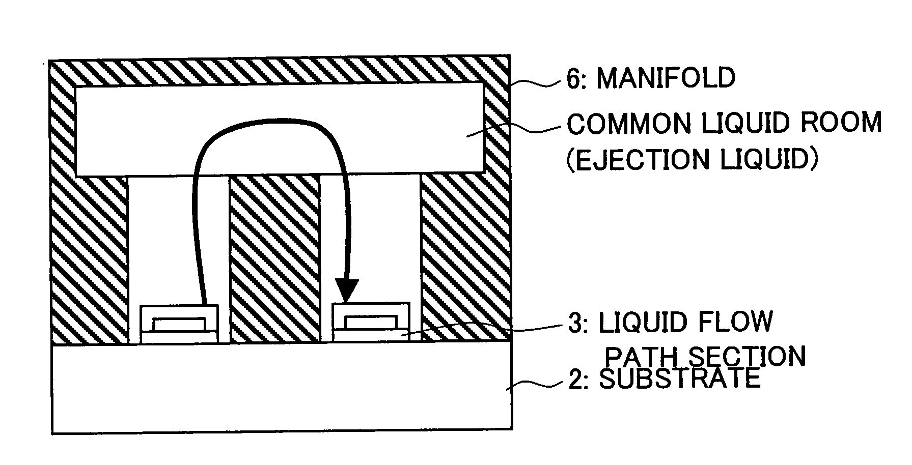
[0034] With this configuration, the inkjet head is provided with the outer shell being disposed on the substrate and forming the liquid flow path section. The inkjet head according to the present invention, therefore, allows easy design change in the shape of the outer shell on the substrate by changing in the pattern or the like.
[0035] Therefore, the inkjet head of the present invention can have a greater degree of freedom in designing the shape of the liquid flow path section.
[0037] According to the method, the filler member is formed on the surface of the substrate. Thus, a shape of the filler member as desired can be easily attained by etching. Moreover, a shape of the upper flow path layer that conceals the filler member with the surface of the substrate can be attained easily by etching.
[0038] As described above, the method according to the present invention can improve the degree of the freedom in designing, because it makes it possible to have a desired shape of the liquid flow path or a desired shape of the upper flow path layer easily.

Problems solved by technology

Production process for such a deep hole formation is highly complicated.
This increases production cost of the inkjet head and makes it difficult to stably produce the inkjet head in the inkjet printers disclosed in Patent Literatures 1 to 4.
In addition to the difficulty of the production process for deep hole formation, the configurations of Patent Literatures 1 to 4 are limited in terms of the plating in that the plating bottom parts of the deep holes is difficult.

Method used


Image

  • Inkjet Head And Method For Manufacturing The Same
  • Inkjet Head And Method For Manufacturing The Same
  • Inkjet Head And Method For Manufacturing The Same

Examples


Embodiment Construction

[0108] One present embodiment of the present invention is described below in reference to drawings.

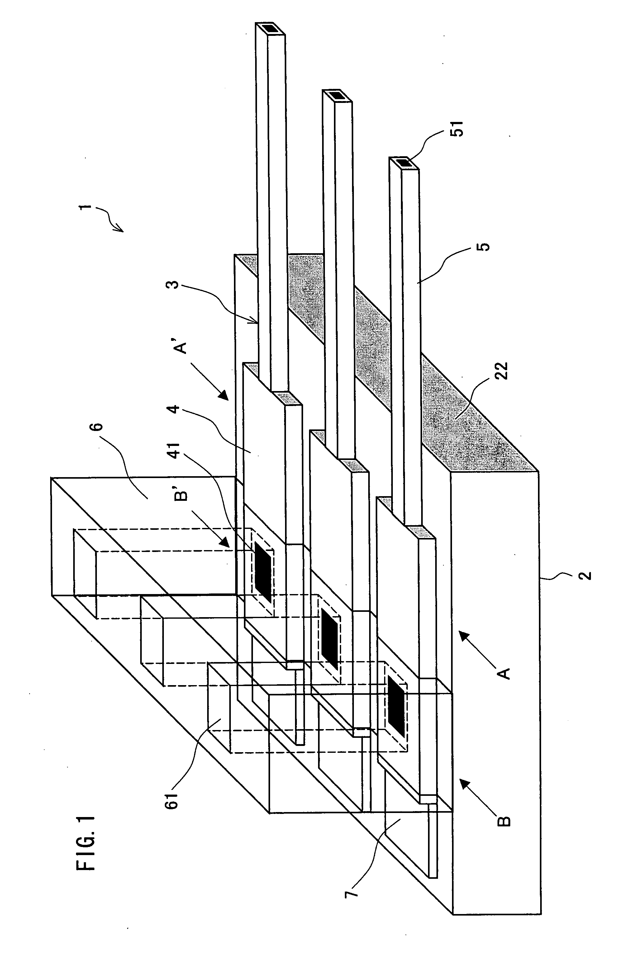
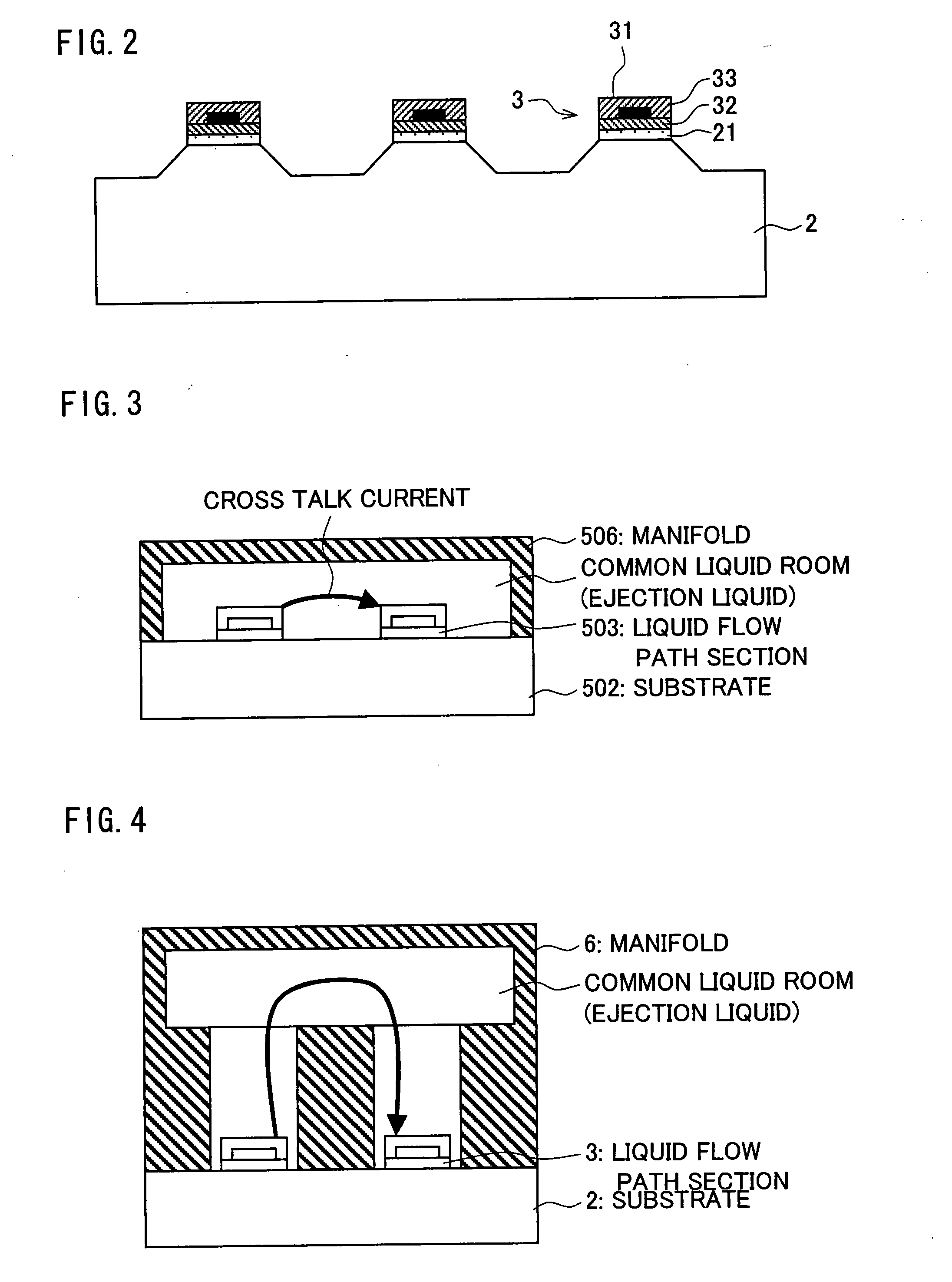
[0109] Firstly, an inkjet head 1 according to the present embodiment is described in terms of its structure referring to FIGS. 1 and 2. FIG. 1 illustrates the present embodiment of the present invention, and is a perspective view schematically illustrating the structure of the inkjet head 1, whereas FIG. 2 is a cross sectional view taken on line A-A′ of the inkjet head illustrated in FIG. 1.

[0110] (Structure of Inkjet Head)

[0111] The inkjet head 1 according to the present embodiment is configured to eject fine liquid droplets to a print target object. More specifically, the inkjet head 1 is a head of a so-called electrostatic ejection type inkjet, which ejects the liquid droplets by electrostatic repulsion caused by electric field application on the liquid droplets. In the inkjet head 1, voltage application results in concentration of an electric field in the vicinity of an outlet 5...


PUM


Abstract

An inkjet head (1) has a liquid flow path section (3) for receiving liquid and, in response to application of a voltage, ejecting the liquid to an object on which a drawing is to be made. The degree of design freedom of the shape of the liquid channel section (3) or the shape of a liquid channel in the liquid channel section (3) can be improved because the liquid channel section (3) is formed on the upper surface of a substrate. Furthermore, the inkjet head can have a structure corresponding to the properties of liquid to be ejected or to an object to which the liquid is to be ejected.

Description

TECHNICAL FIELD [0001] The present invention relates to inkjet heads, each of which ejects liquid to print a fine pattern of fine dots and manufacturing methods of such heads. BACKGROUND ART [0002] So-called “inkjet printers” are widely used now to print characters, or images, etc. on sheets or the other article. The inkjet printer prints by spraying print paper with fine droplets of ink. [0003] Recent applications of the inkjet printer technology are found in, among others, the forming of fine patterns on liquid crystal display color filters and conductor patterns on printed wiring boards. Conventionally, these patterns were formed by photolithography. [0004] Active development programs are being implemented to apply the inkjet technology to, for example, fine dot forming devices which are able to form fine patterns with high accuracy by applying fine ink dots to a print target object (for example, a liquid crystal display color filter or a printed wiring board). [0005] The fine do...

Claims


Application Information

Patent Timeline
Patent Type & Authority Applications(United States)
IPC IPC(8): B41J2/05
CPCB41J2/1433B41J2/1623B41J2/162
Inventor DEGUCHI, HARUHIKONISHIO, SHIGERUKAWAI, HIDETSUGU
Owner SHARP KK
Learn More