Vacuum Processing Chamber for Very Large Area Substrates

a technology of pecvd and processing chamber, which is applied in the direction of chemical vapor deposition coating, coating, plasma technique, etc., can solve the problems of aluminum alloys showing creep deformation, non-uniform deposition on the substrate, and becoming more and more difficult to keep the inner reactor substantially fla

Inactive Publication Date: 2008-02-28
OERLIKON SOLAR AG (TRUEBBACH)
View PDF13 Cites 318 Cited by
  • Summary
  • Abstract
  • Description
  • Claims
  • Application Information

AI Technical Summary

Benefits of technology

[0012] A plasma reactor for PECVD treatment of large-size substrates according to the invention will comprise a vacuum process chamber 19 as an outer chamber and at least one inner reactor with process gas feed 22 and a RF feed 24 electrically connected to an electrode showerhead 25 acting as RF antenna, said inner reactor again comprising a reactor bottom 6 and a reactor top 2, being sealingly connected at least during treatment of substrates in the plasma reactor and separated at least during loading / unloading of the substrates. Further useful embodiments and features are described below and in respective dependant claims.

Problems solved by technology

With the appearance of larger and larger substrates (over 2 m×2 m) however, it becomes more and more difficult to keep the inner reactor substantially flat and consequently to be able to comply with the required production specifications and to load and unload the substrates.
Unfortunately however, aluminum alloys tend to exhibit creep deformation at elevated temperatures and even creep resistant alloys cannot fully eliminate such deformation over time.
Any deformation and deviation from flatness of the reactor also causes non uniform deposition on the substrate, since the deposition rate is (among other factors) a function of the plasma gap—i.e. the distance between the top and bottom electrodes of the reactor.
The biggest disadvantage of the current reactor design is the side-slit / fork / pin-type of loading and unloading the substrates as described above.
With very large substrate sizes however, the fork tends to bend under the combination of its own weight and the substrate weight.
Simple stainless steel stiffeners, such as T- or H shaped bars as known in the art, cannot fully compensate the deformation and distortion of very large reactors, especially when these reactors reach side lengths of over two meters.
Simple stiffeners would not only fail to provide a flat reactor at room temperature, but especially so at operating temperature, since even stainless steel tends to loose strength at elevated temperature.
The aforementioned issues, resulting mainly from different form accuracy issues that must be faced when using large reactor sizes of more than 2 meter side length, ask for a new reactor design.
The new reactor design has to meet requirements of optimal height while processing the substrate and the aforementioned loading issue resulting from the loading fork being bent.
These requirements are no longer fulfilled by the traditional reactor design.
Additionally, the reactors achieve larger and larger dimensions and have to comply with increasing deformation and expansion issues.

Method used


Image

  • Vacuum Processing Chamber for Very Large Area Substrates
  • Vacuum Processing Chamber for Very Large Area Substrates
  • Vacuum Processing Chamber for Very Large Area Substrates

Examples


Embodiment Construction

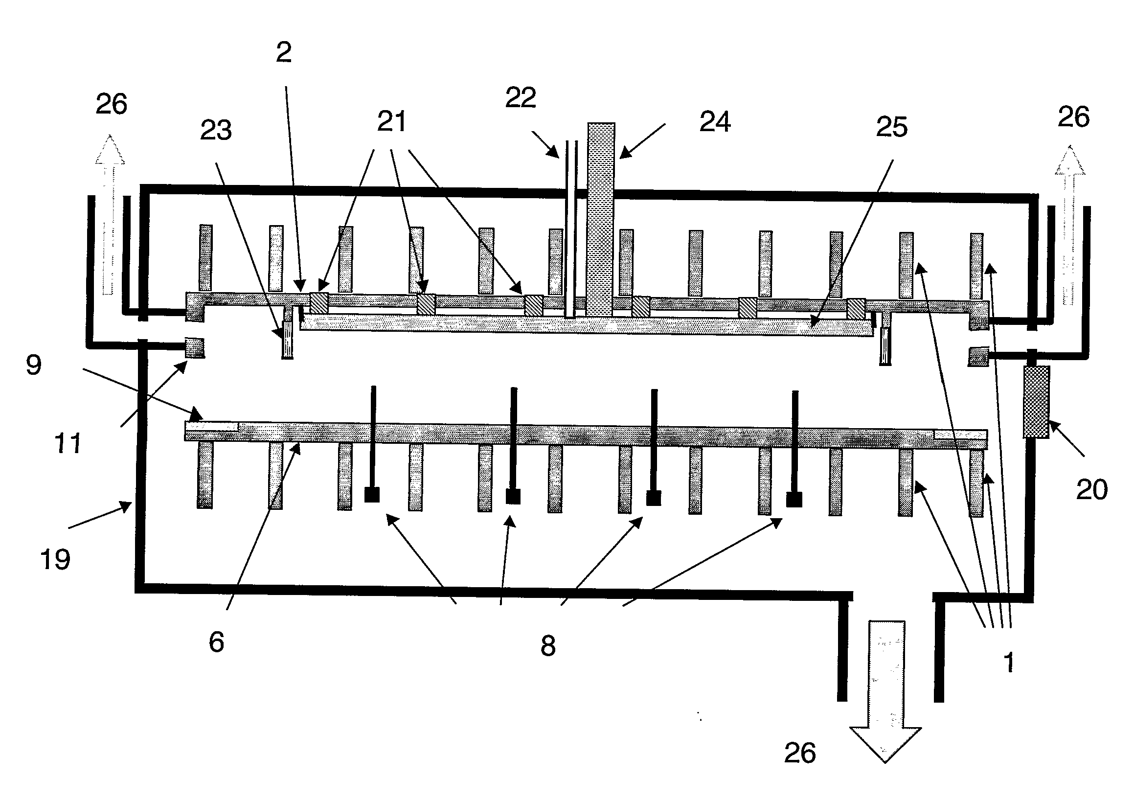
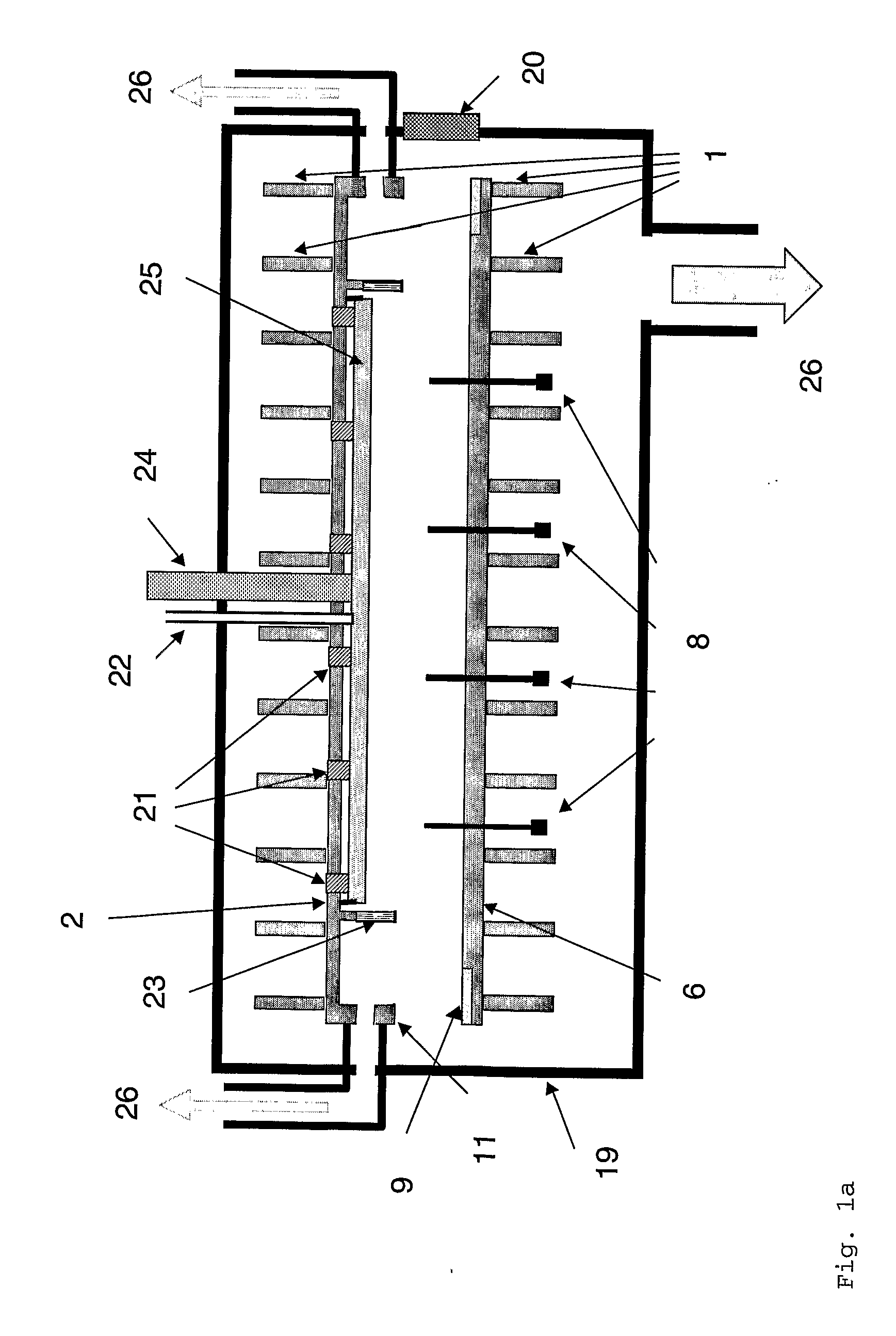
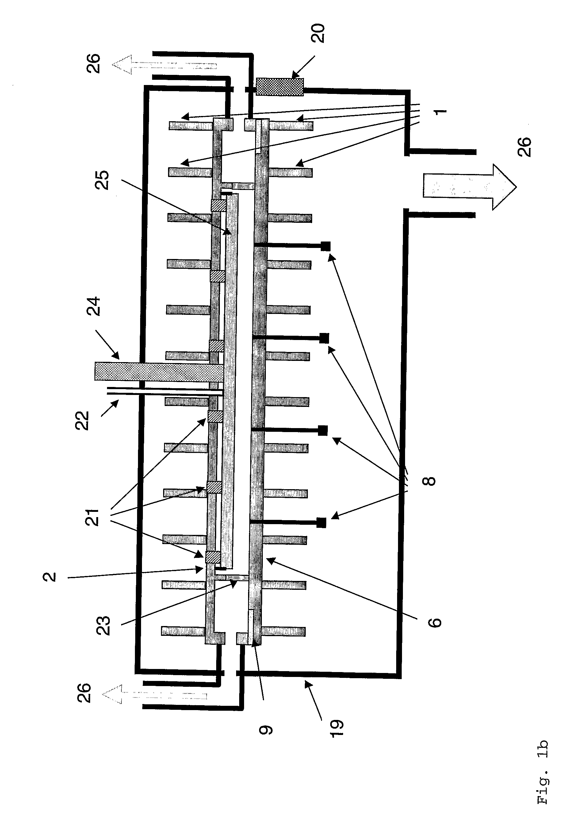
[0019] Therefore, the present invention is based on a new reactor concept. The reactor is divided in two parts; a reactor bottom 6 and a reactor top 2 (see FIG. 1). The reactor top 2 is attached to the outer vacuum process chamber 19 preferably by stiffeners 1 (connection not shown in FIG. 1). The reactor bottom 6 (or bottoms in the case of multiple reactor systems in a single outer chamber) is movable vertically such that a slit opens between the reactors side wall 11 and the sealing plate 9. When the reactor is fully opened the slit broadens and the lifting pins 8 start sticking out. The loading fork (not shown in FIG. 1) is then able to deposit the substrate on the lifting pins for loading, or to retract the substrate from the lifting pins 8 by lifting the substrate from underneath through the chamber gate valve 20. This “inverted shoe box” type of opening has the major advantage that the height of the reactor walls 11 and thus accordingly the plasma gap can be relatively small. ...


PUM

PropertyMeasurementUnit
temperatureaaaaaaaaaa
lengthsaaaaaaaaaa
temperatureaaaaaaaaaa

Abstract

A plasma reactor for PECVD treatment of large-size substrates according to the invention comprises a vacuum process chamber as an outer chamber and at least one inner reactor with an electrode showerhead acting as RF antenna, said inner reactor again comprising a reactor bottom and a reactor top, being sealingly connected at least during treatment of substrates in the plasma reactor and separated at least during loading/unloading of the substrates. Further embodiments comprise a sealing for said reactor to/bottom and a suspender for the RF antenna/electrode showerhead.

Description

[0001] This invention relates to vacuum processing equipment for very large area substrates, especially a PECVD process chamber (respectively an inner reactor) with compensation means for the deviation from flatness. BACKGROUND OF THE INVENTION [0002] The present invention relates to large area PECVD process chambers in general and to such chambers which themselves are enclosed again in a second surrounding vacuum chamber in particular. Such “boxes within a box”, (Plasma Box™) are known in the art and described in U.S. Pat. No. 4,798,739. The major advantage of such “boxes within a box” is that a lower pressure may be maintained in the outer airtight chamber than within the inner reactor chamber such that a controlled gas flow may be maintained from the inner- to the outer chamber (“differential pumping”). A further advantage of such a “boxes within a box” system is that the inner chamber may be maintained at a constant process temperature of typically around 250-350° C. (isothermal...

Claims


Application Information

Patent Timeline
Patent Type & Authority Applications(United States)
IPC IPC(8): C23C16/00H05H1/24
CPCC23C16/4409C23C16/509H01J2237/3325H01J37/32082H01J37/32458C23C16/54C23C16/00
Inventor AING, PHANNARADELAUNAY, LAURENTJOST, STEPHANELYAAKOUBI, MUSTAPHA
Owner OERLIKON SOLAR AG (TRUEBBACH)
Why Eureka
Try Eureka