Process for holding an optical lens on a holder of a lens machining equipment

a technology of machining equipment and optical lens, which is applied in the direction of grinding machine components, grinding/polishing apparatus, grinding machines, etc., can solve the problems of preventing accurate machining, affecting the quality of the lens, and altering the lens material, etc., and achieves the effects of easy removal of the optical element, high production rate, and very cheap materials

Inactive Publication Date: 2008-02-28
ESSILOR INT CIE GEN DOPTIQUE
View PDF13 Cites 32 Cited by
  • Summary
  • Abstract
  • Description
  • Claims
  • Application Information

AI Technical Summary

Benefits of technology

[0018]Using a pressure sensitive adhesive for sticking the optical element to the wafer enables easy removal of the optical element from the holder of the machining equipment. This can be achieved in a two-step process. First, the vacuum in the cavity of the suction chuck is suppressed, so that the optical element together with the wafer is removed from the suction chuck. Then, the wafer is removed from the convex surface of the optical element.
[0019]An advantage of a process according to the invention results from ...

Problems solved by technology

Then, such lens deformation prevents from achieving accurate machining, and may also alter the lens material.
Furthermore, such method with heating steps is time-consuming and costly.
Such method involves in general toxic alloys, generates waste, in particular contamined wax and alloys.
For example, U.S. Pat. No. 3,994,101 discloses using a suction chuck, but this method may create lens deformation, especially when the ...

Method used


Image

  • Process for holding an optical lens on a holder of a lens machining equipment
  • Process for holding an optical lens on a holder of a lens machining equipment

Examples


Embodiment Construction

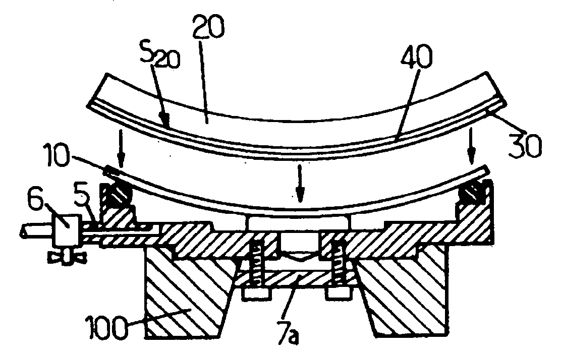
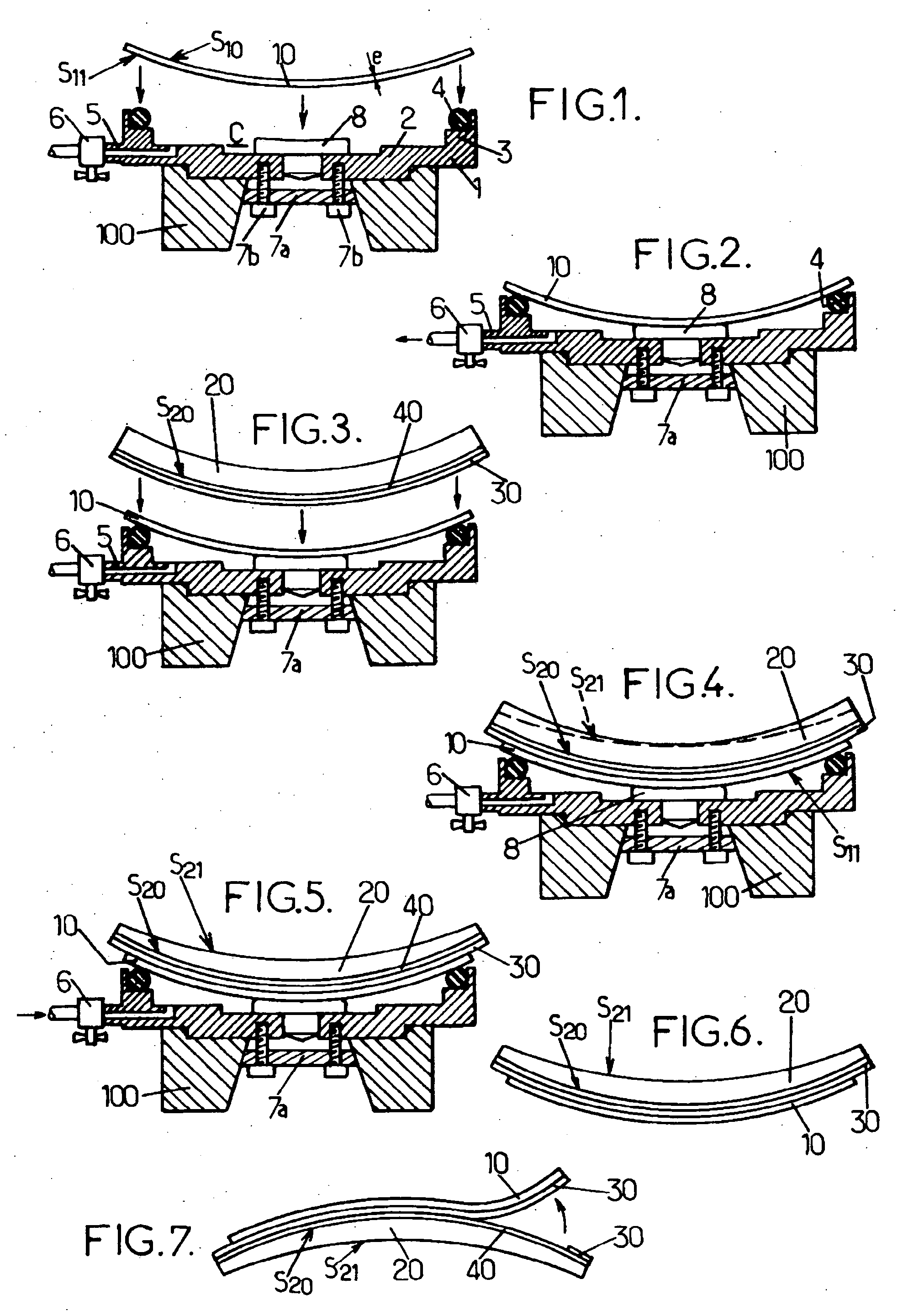
[0033]On FIG. 1, reference 1 refers to a suction chuck according to the invention. It comprises a bottom part 2 and a side wall 3 of generally cylindrical shape, so as to form an inner cavity C. The side wall 3 has a limited height, so that the suction chuck 1 can be easily fitted on a holder 100 of a lens machining equipment. Such lens machining equipment may be a lens surface generating machine, a lens polishing or fining machine, an edging machine, etc. In particular, it can be fitted on machines such as LOH's V95 or Toro-X-S / SL. Chuck 1 can be, for example, made of aluminum for light-weight purpose, or any other rigid material. Self-centering part 7a and screws 7b allow tight fixing of the suction chuck 1 onto the holder 100, but other equivalent systems may be used, depending on the actual holder 100.

[0034]The side wall 3 is provided with an O-ring seal 4 at its end opposite the bottom part 2. It is also provided on a side with an air conduct 5 which connects the cavity C to a ...


PUM


Abstract

A process is provided for rapidly holding an optical article having a convex surface on a holder of a lens machining equipment, the holder being equipped with a suction chuck comprising a cavity with a side wall and sealing means on a front end of the side wall, comprising the following steps: /a/ providing a flexible curved wafer with a concave surface arranged to close the cavity at the front end of the side wall; /b/ a fixing step in which the wafer is fixed onto the holder by providing vacuum between the concave surface of the wafer and the suction chuck; and /c/ a pressing step in which the concave surface of the optical article is pressed onto the concave surface of the wafer, an adhesive material being arranged between the wafer and the optical article The assembly is tight enough for sustaining machining forces, and the lens can be released rapidly.

Description

FIELD OF THE INVENTION[0001]The invention relates to a process for holding an optical article, for example a lens, on a holder of a lens machining equipment. In particular, it is useful when manufacturing an ophthalmic lens.BACKGROUND OF THE INVENTION[0002]When producing an optical lens, and especially an ophthalmic lens, it is necessary to fix the lens on the holder of a machining equipment for machining the lens. For example, the machining corresponds to the lens surface generating step, the fining step, the polishing step or the edging step in the lens production process. For an ophthalmic lens, such production steps are carried out in a prescription lab where a semi-finished lens is machined so as to obtain a spectacle lens which corresponds to the ametropy of a lens carrier.[0003]Usually, a wax or an alloy is used for fixing firmly the semi-finished optical lens on the equipment holder. The wax or alloy connects the convex surface of the semi-finished lens to an end part of the...

Claims


Application Information

Patent Timeline
IPC IPC(8): B24B13/00
CPCB24B13/005B24B9/146
Inventor JIANG, PEIQIGLACET, ARNAUDPEACOCK, GEVAN
Owner ESSILOR INT CIE GEN DOPTIQUE
Why Eureka
Try Eureka