Variable compression ratio internal combustion engine

Inactive Publication Date: 2008-03-06
TOYOTA JIDOSHA KK
View PDF6 Cites 19 Cited by
  • Summary
  • Abstract
  • Description
  • Claims
  • Application Information

AI Technical Summary

Benefits of technology

[0014]It is an object of the invention to provide a variable compression ratio internal combu

Problems solved by technology

As a result, there is possibility that the friction force between the wall surface defining the cylinder bore and the piston may increase, and the fuel econom

Method used


Image

  • Variable compression ratio internal combustion engine
  • Variable compression ratio internal combustion engine
  • Variable compression ratio internal combustion engine

Examples


first embodiment

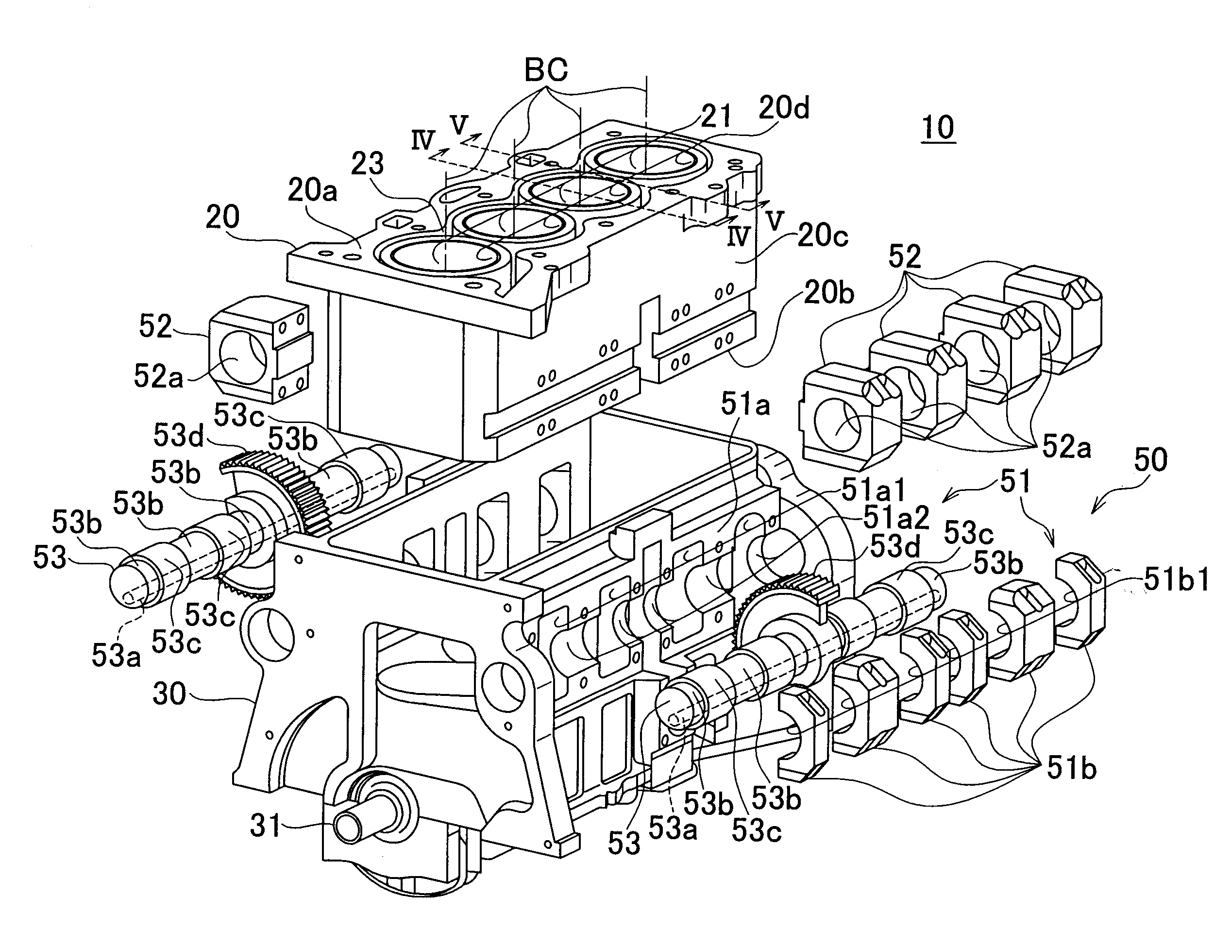
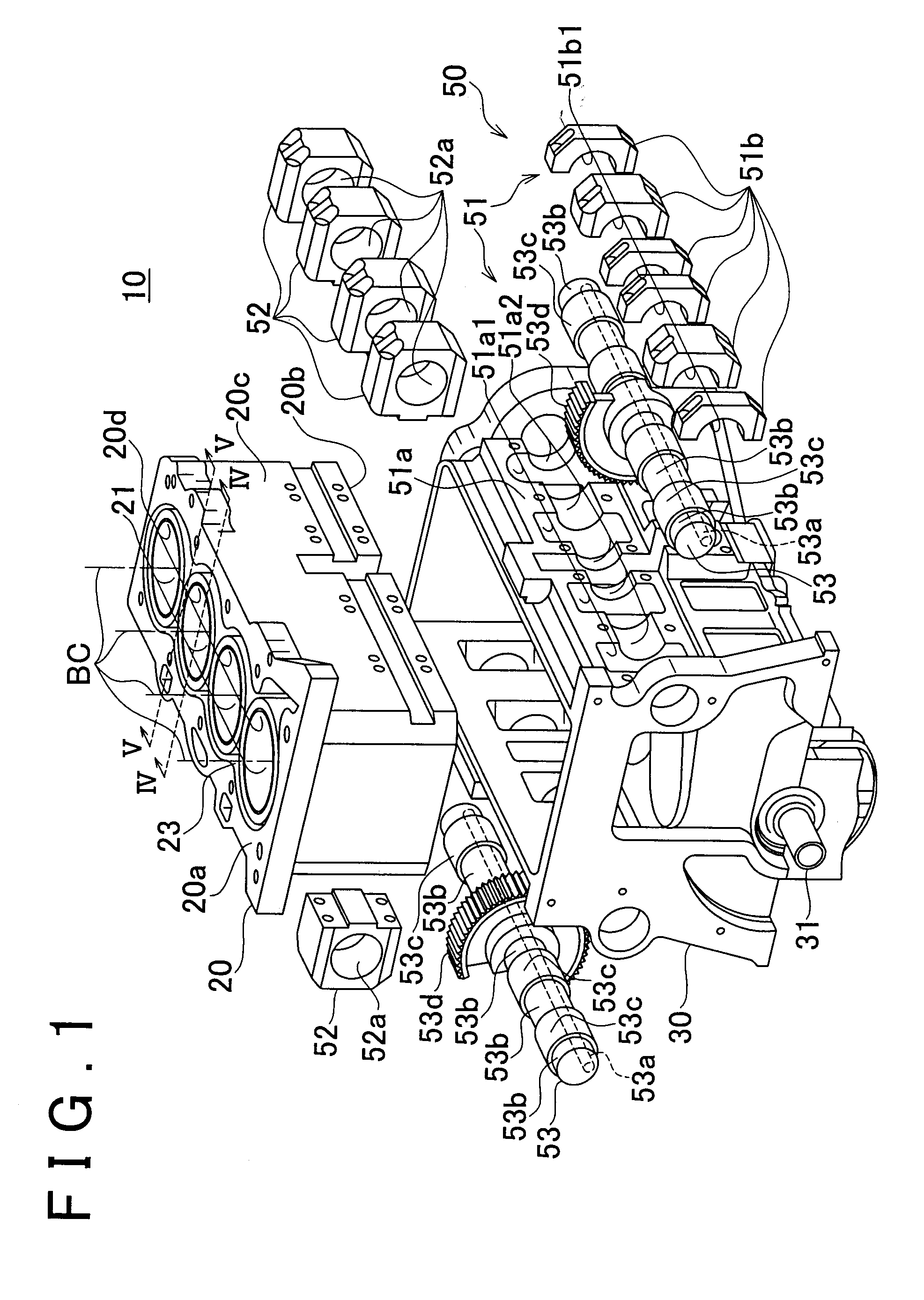
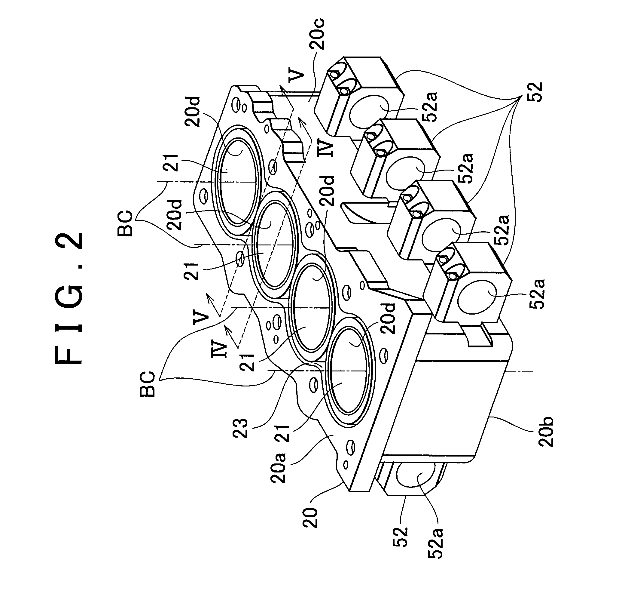
[0086] In the variable compression ratio internal combustion engine 10 in accordance with the first embodiment constructed as described above, when a mixture gas formed in a combustion chamber 41 burns, the pressure of gas in the combustion chamber 41 becomes very high. Due to this pressure, the lower surface 40a of the cylinder head 40 is pressed upward by a force F0a, and the top surface of the piston 22 is pressed downward by a force F0b. Therefore, a force F1a in the upward direction is exerted on the cylinder block 20 to which the cylinder head 40 is fixed, and a force F1b in the downward direction is exerted on the crankcase 30 that supports the crankshaft 31 linked to the piston 22. As a result, crankcase 30-side portions of the wall surfaces that define the bearing holes 52a of the block-side bearing-forming portions 52 receive a force F2 caused by the shaft-shaped drive portion 53, and are therefore pressed downward.

[0087]Since the force F2 acts at a position that is apart ...

second embodiment

[0103]According to the variable compression ratio internal combustion engine 10 in accordance with the second embodiment constructed as described above, when the block-side bearing-forming portions 52 press the outer wall surface 20c of the cylinder block 20 as described above, a stress having substantially the same magnitude as the aforementioned outer wall surface stress occurs in a portion of the cylinder block 20 that is on the outer wall surface 20c side of the reinforcement member 64 (outer wall surface-side portion of the cylinder block 20). At this time, since the rigidity of the reinforcement member 64 is higher than the rigidity of the cylinder block 20, the rigidity of the reinforcement member 64 makes the stress transmitted to the portion of the cylinder block 20 on the bore wall surface side of the reinforcement member 64 (the bore wall surface-side portion, i.e., the cylinder liners 20d) smaller than the outer wall surface stress. Therefore, the bore wall surface stres...

third embodiment

[0112]According to the variable compression ratio internal combustion engine 10 in accordance with the third embodiment constructed as described above, the cylinder block 20 has higher rigidity in the portions where a block-side bearing-forming portion 52 extends out than in other portions. Therefore, even when the pressing force F3 is exerted, the cylinder block 20 is unlikely to deform. That is, it becomes possible to make small the degree of the deformation of the bore wall surface caused by the pressing force F3 while restraining the increase in the weight of the cylinder block 20.

[0113]As described above, each of the variable compression ratio internal combustion engines according to the foregoing embodiments has a deformation-supressing structure. For example, the stress reduction groove portion, the structure of the cylinder block in which the position of the bore wall surface lower end is the same as the position of the block outer wall surface lower end, and the protruded p...


PUM


Abstract

An internal combustion engine includes a variable compression ratio mechanism made up of a case-side bearing-forming portion, a block-side bearing-forming portion, and a shaft-shaped drive portion. The case-side bearing-forming portion is formed in an upper portion of a crankcase. The block-side bearing-forming portion extends outward from a lower end portion of an outer wall surface of the cylinder block. The block-side bearing-forming portion is linked to the case-side bearing-forming portion by the shaft-shaped drive portion. Slit-shaped stress reduction groove portions each having an opening in a region between the block-side bearing-forming portion and cylinder bores are formed in a lower surface of the cylinder block. Therefore, even when the block-side bearing-forming portion presses the outer wall surface, the stress reduction groove portions reduce the stress, so that the deformation of the wall surface of each cylinder bore can be restrained.

Description

INCORPORATION BY REFERENCE[0001]The disclosure of Japanese Patent Application No. 2006-242150 filed on Sep. 9, 2006 including the specification, drawings and abstract is incorporated herein by reference in its entirety.BACKGROUND OF THE INVENTION[0002]1. Field of the Invention[0003]The invention relates to a variable compression ratio internal combustion engine capable of changing the compression ratio that is the ratio of the maximum value to the minimum value of the volume of a combustion chamber that changes with the movement of the piston.[0004]2. Description of the Related Art[0005]Variable compression ratio internal combustion engines have been proposed which change the compression ratio by moving the cylinder block relative to the crankcase in the direction of an axis (center axis) of a cylinder bore (hereinafter, simply referred to also as “up-down direction”). For example, one of the variable compression ratio internal combustion engines has a cylinder block that is dispose...

Claims


Application Information

Patent Timeline
IPC IPC(8): F02B75/04
CPCF02B75/041
Inventor KAMIYAMA, EIICHI
Owner TOYOTA JIDOSHA KK
Why Eureka
Try Eureka