

Broad band antenna
a broad band antenna and antenna technology, applied in the direction of antennas, antenna details, elongated active element feed, etc., can solve the problems of not being able to achieve the characteristics of the antenna, the size of the antenna is not suitable for the small-sized antenna, and the current needed antenna characteristics are difficult to achieve. , to achieve the effect of a big gain drop
- Summary
- Abstract
- Description
- Claims
- Application Information
AI Technical Summary
Benefits of technology
Problems solved by technology
Method used
Image

Examples
example 1
[0033] In first example, antennas were manufactured with materials satisfying permittivity, permeability and magnetic loss characteristics. Then, radiation efficiency, bandwidth and a size reduction ratio of the antennas were measured to confirm improvement effects according to the present embodiment.
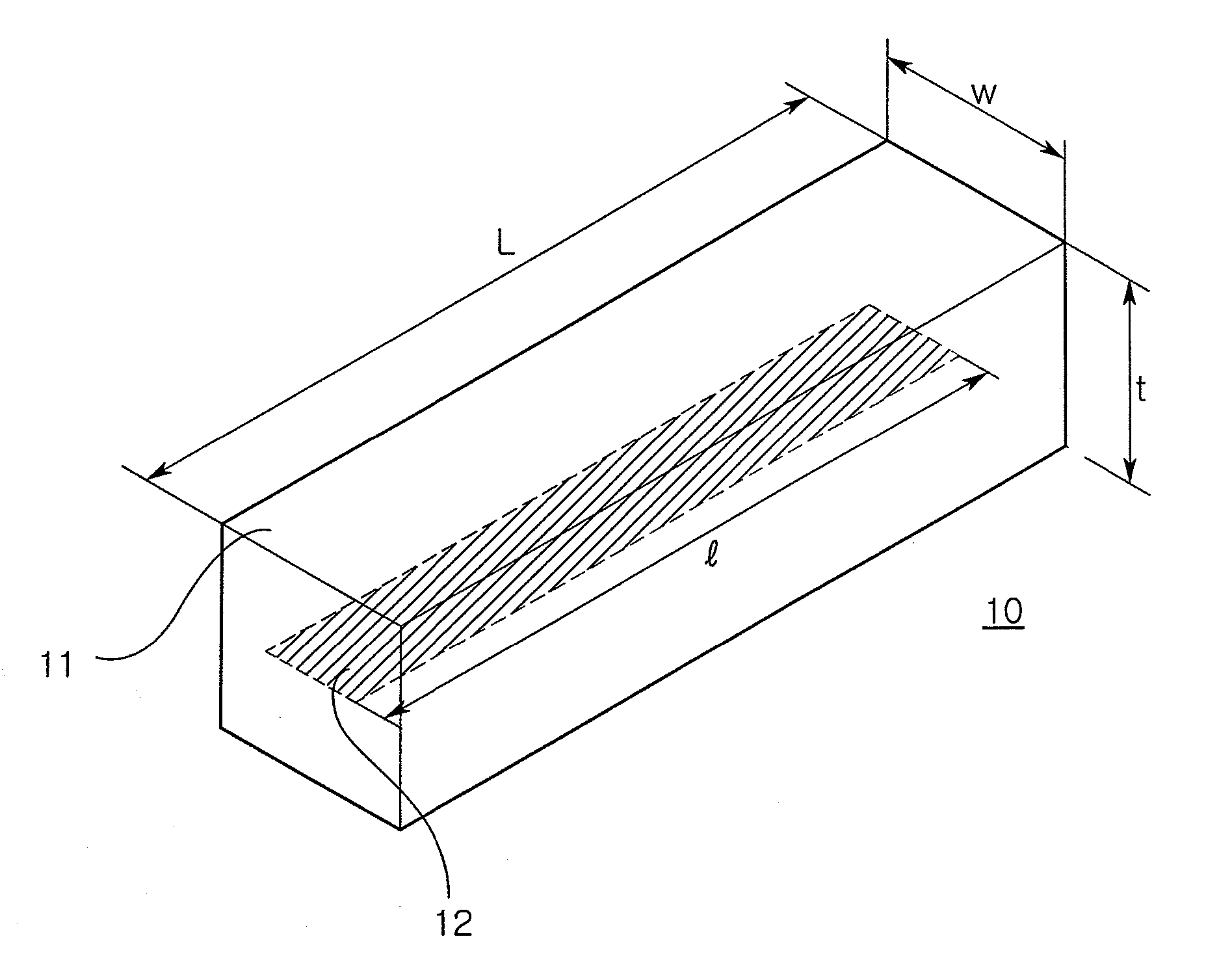
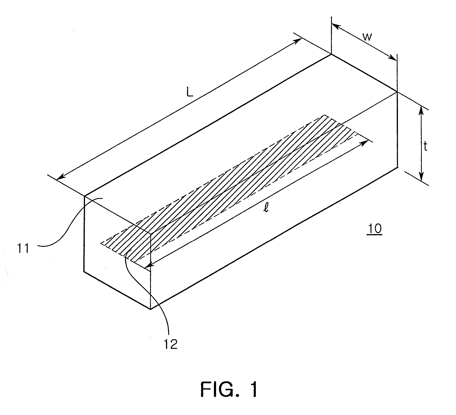
[0034] In the first example, body-forming materials were constructed to carry maximum properties to identify subsequent effects therefrom. The first example adopted as a basic model a monopol antenna including a rectangular parallelepiped block 11 (L×W×T=73×4×4 cm) surrounding a radiator, i.e., Cu conductive line 12. Then, the body-forming materials noted in Table 1 were prepared to be manufactured into respective rectangular parallelepiped blocks and then antennas each satisfying a central frequency band of 520 MHz.
[0035] As seen in Table 1, composite materials of dielectric and magnetic substances or sintered magnetic substances employed in Inventive Examples 1 to 6 satisfy permitti...
example 2
[0050] In second example, carbonyl iron powder and a silicon resins were mixed at adequate ratios to prepare soft magnetic composite materials used in antenna bodies (40×10×2.5 mm).
[0051] That is, the carbonyl iron powder and the silicone resin were mixed at a ratio of 1:1(C1), 3:1(C2), and 5:1(C3), respectively. The carbonyl iron powder was added by 50 wt %, 66.5 wt %, and 83.3 wt % with respect to a total weight of each of the soft magnetic composite materials.
[0052] Similarly to the results of Example 1, a higher ratio of the carbonyl iron powder increased permittivity and permeability (magnetic loss), thereby leading to a low band frequency, i.e., size reduction effects.
[0053] In antennas manufactured according to the second example, VSWR and gain thereof are influenced by not only magnetic loss of the materials but also permittivity and permeability and thus shown a bit complicated. The antennas exhibit somewhat high gain at a usable frequency band with a VSWR of 3 or less. ...
example 3
[0055] In third example, a NiZn ferrite powder and a silicone resin were mixed at adequate ratios to prepare soft magnetic composite materials used in antenna bodies (40×10×2.5 mm).
[0056] That is, the NiZn ferrite powder and the silicone resin were mixed at a ratio of 3:1(N1), 5:1(N2), 7:1(N3), and 9:1(N4), respectively. When converted into weight percent, the NiZn ferrite powder is construed to be added at a varying ratio of 50 wt % to 90 wt %.
[0057] In general, the NiZn ferrite powder has a magnetic loss tangent higher than those of other magnetic powders, e.g., carbonyl iron, thus expected to be limited in its use. Meanwhile, in a case where the NiZn ferrite powder is mixed with the silicone resin of polymer into the soft magnetic composite materials to be applied to antennas as designed in FIG. 3, the antennas exhibit relatively lower gain as shown in FIG. 5A.
[0058] However, this low level can be improved to a desired level by a simple matching circuit. Therefore, the antenna...
PUM
| Property | Measurement | Unit |
|---|---|---|
| relative permittivity | aaaaa | aaaaa |
| relative permittivity | aaaaa | aaaaa |
| relative permittivity | aaaaa | aaaaa |
Abstract
Description
Claims
Application Information