Radiant heater

Inactive Publication Date: 2008-03-06
COOPER RICHARD
View PDF24 Cites 22 Cited by
  • Summary
  • Abstract
  • Description
  • Claims
  • Application Information

AI Technical Summary

Benefits of technology

[0005]After the resistive material is applied and cured, spaced apart electrodes or bus-bars are applied to apply a voltage across the patterned resistive material. A protective coating such as Teflon® or silicon is then applied over the resistive material to protect it from moisture and to provide an electrically insulative layer.

Problems solved by technology

During the curing process it is necessary to control the process so that the cement backer board is not heated sufficiently to degrade the materials within the backer board.

Method used


Image

  • Radiant heater
  • Radiant heater
  • Radiant heater

Examples


Embodiment Construction

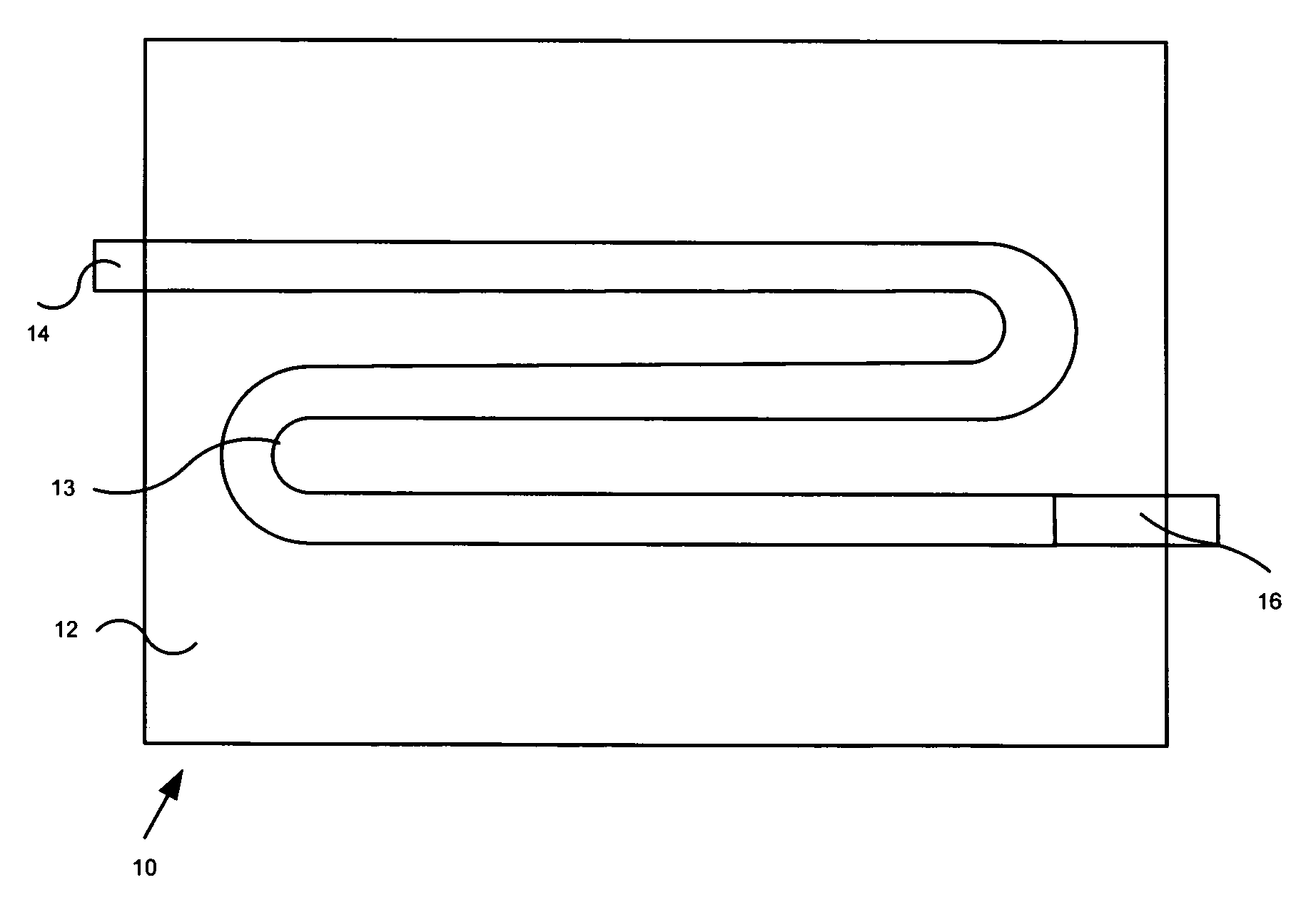
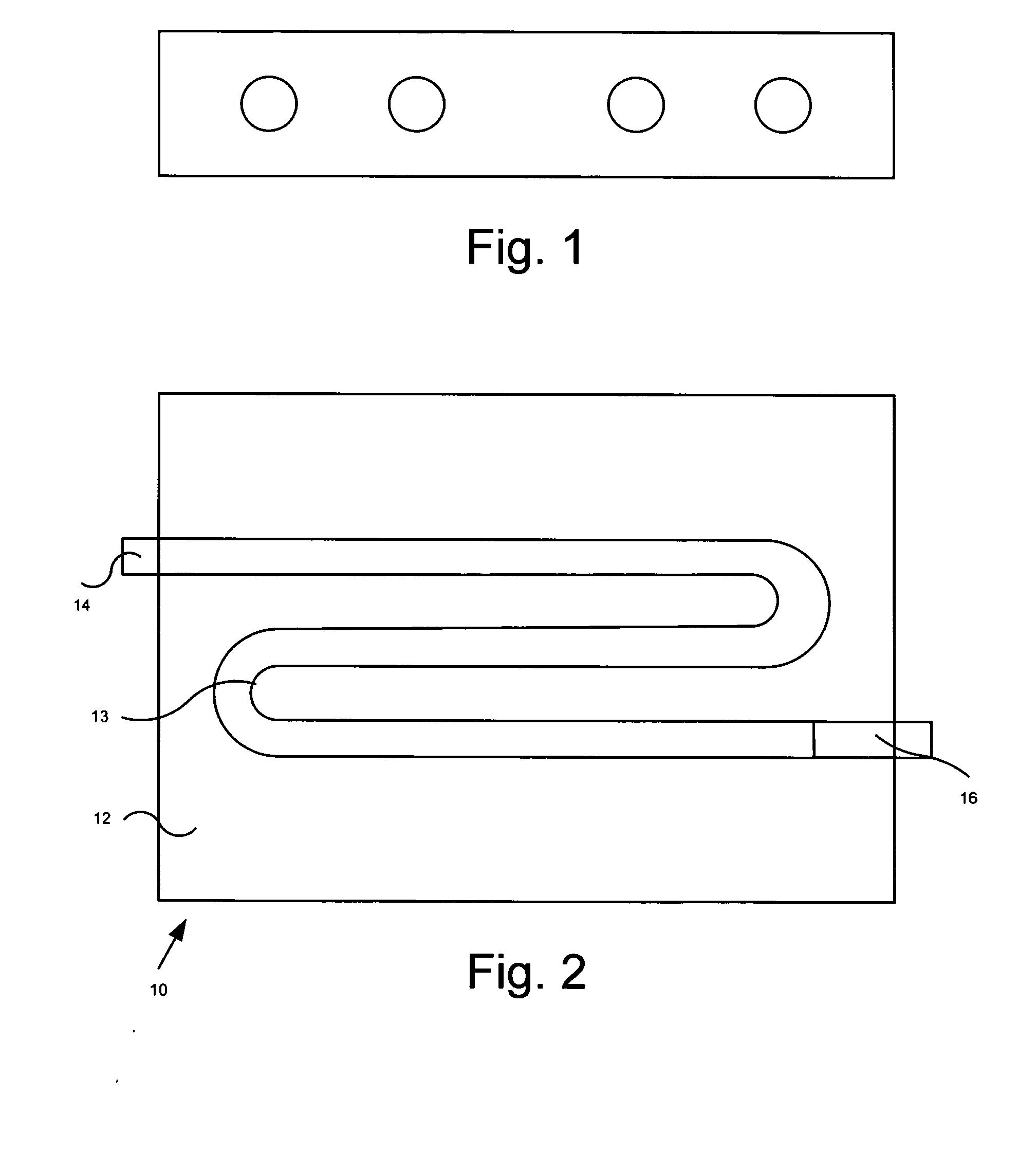
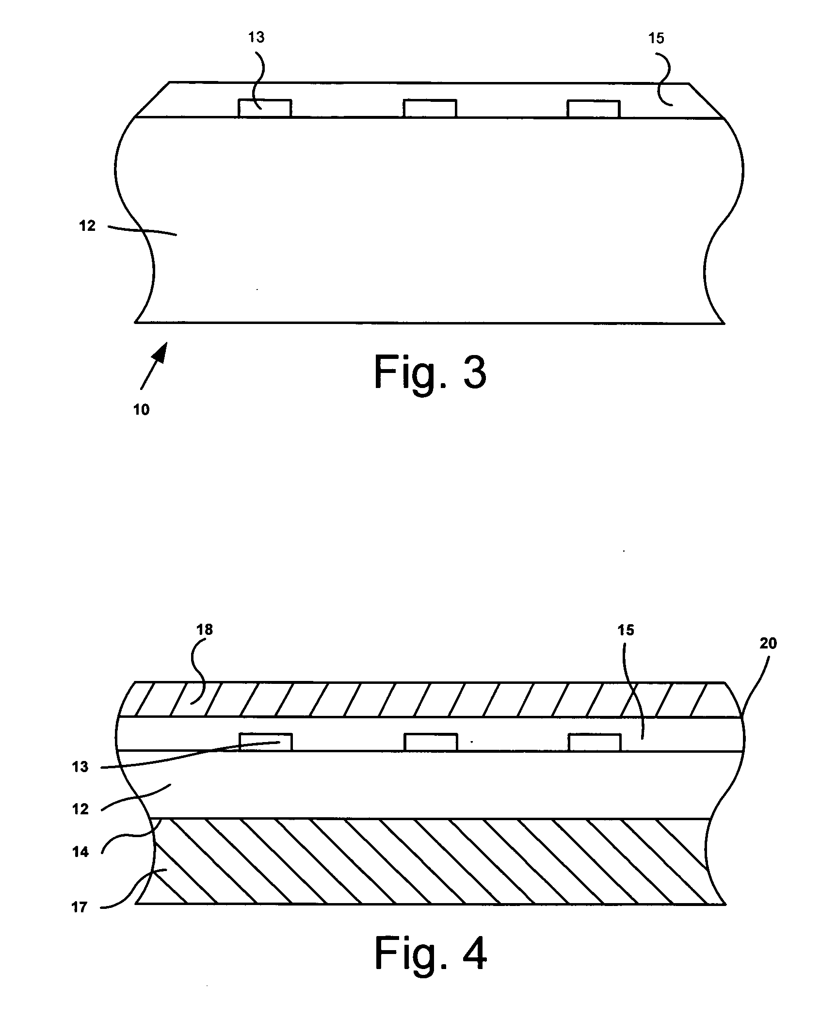
[0013]Referring now to FIGS. 2-4, a preferred embodiment of the invention is shown generally at 10, and includes a backer board substrate 12, a patterned resistive material 13 disposed on the substrate 12, and interconnects 14 and 16. Backer board may be any of a number of materials, but in the preferred embodiment it is formed of a cementous material, and which is designed to underlay tile or other floor finish materials. One such product is known as Hardy Board®.

[0014]In one embodiment the patterned resistive film is a graphite impregnated sol-gel material such as that manufactured by either ThermoCeramix, Inc. of Shirley Mass. or Datec Coating Corporation of Milton, Ontario, Canada. The resistive material is applied directly to the backer board through a means of spraying, painting or silk screening onto the surface of the substrate that will support the tile or other outer finish material. Other methods of applying a resistor include the thermal spraying of the resistive materia...


PUM

PropertyMeasurementUnit
electrically resistiveaaaaaaaaaa
electrical currentaaaaaaaaaa
conductiveaaaaaaaaaa

Abstract

A thick film, large area resistance heater including a substrate having an electrically non-conductive surface on which is deposited a film electrical resistor such as a thermally sprayed, photo resist etched foil or sol-gel graphite based material. A combination of an electrically conductive film coated backer board substrate composed of portland cement, sand, cellulose fibers and other selected additives. A mica substrate heater can be cemented to a cement backer board or a vinyl with adhesive backing.

Description

BACKGROUND OF THE INVENTION[0001]This invention relates to heaters and in particular to a method of heating rooms and spaces through radiant heat from floors, walls and ceilings. There are various known systems and methods used for heating floors. Some include circulating heated water or air through a piping system installed beneath the surface of the floor (FIG. 1). Others include electrically heated insulated wires that are enmeshed in a material placed in between the floor surface and the sub floor, or in a concrete layer that also serves as the finished floor. In other instances a cement board is attached to the sub floor and a finish material such as tile, linoleum or wood are adhered to the cement board. In those systems efficiency is compromised as there is no intimate contact between the source of heat and the surface to be heated. This invention overcomes these shortcomings of the prior art, and provides an improved system for heating surfaces such as floors and walls.SUMMA...

Claims


Application Information

Patent Timeline
Patent Type & Authority Applications(United States)
IPC IPC(8): F24D13/02
CPCY02B30/26F24D13/022Y02B30/00
Inventor COOPER, RICHARD
Owner COOPER RICHARD
Why Eureka
Try Eureka