

Conductive foamed roller, method of producing the same, and image forming apparatus
a foamed roller and conductive technology, applied in the direction of electrographic process, instruments, corona discharge, etc., can solve the problems of permanent deformation and difficulty in obtaining high-quality images, and achieve the effects of reducing environmental load, preventing lateral stream, and reducing permanent compressive deformation
- Summary
- Abstract
- Description
- Claims
- Application Information
AI Technical Summary
Benefits of technology
Problems solved by technology
Method used
Image

Examples
first embodiment
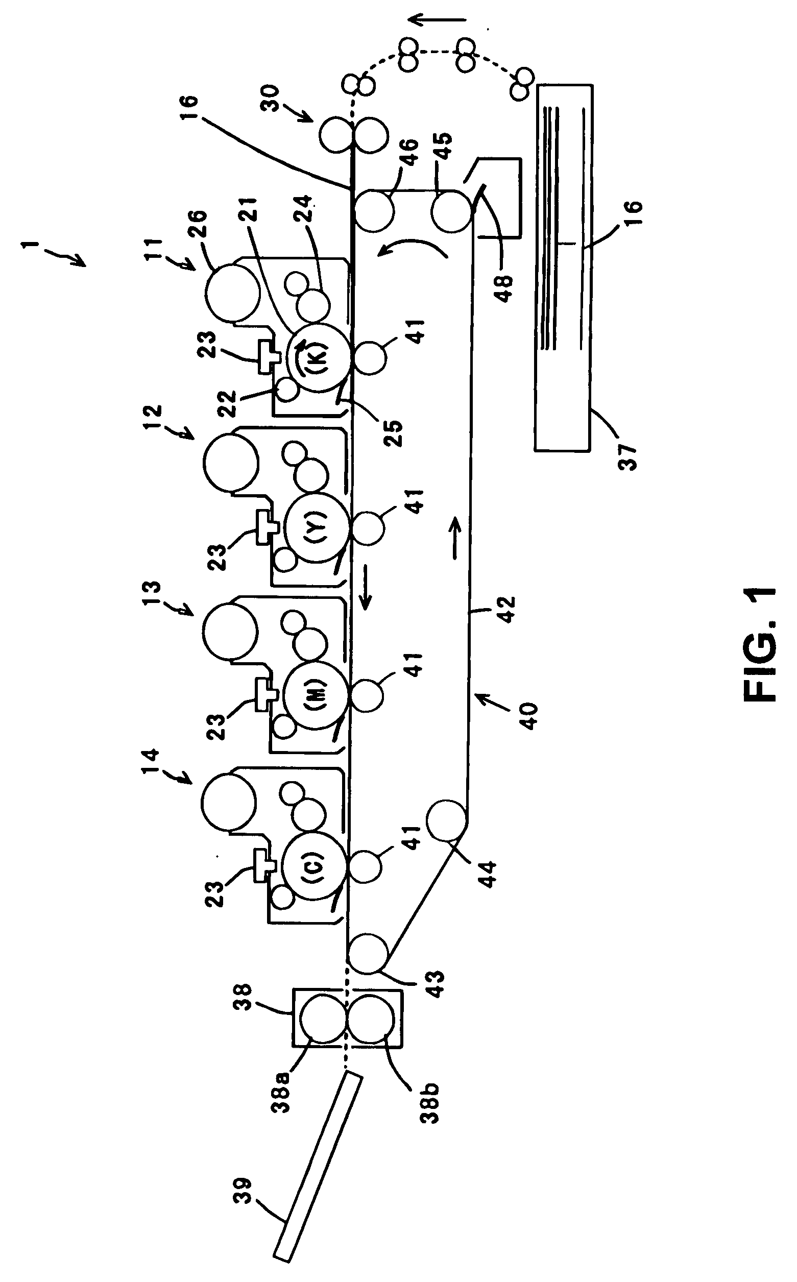
[0032]A first embodiment of the present invention will be explained. FIG. 1 is a schematic view showing an image forming apparatus 1 according to the first embodiment of the present invention. The image forming apparatus 1 has a configuration of a color electric-photography printer capable of printing an image in four colors, i.e., black (K), yellow (Y), magenta (M), and cyan (C).
[0033]As shown in FIG. 1, in the image forming apparatus 1, four image drum units 11 to 14 are disposed along a transport path of a recording sheet 16 as a recording medium in this order from an upstream side of the transport path, so that the image drum units 11 to 14 form images in black (K), yellow (Y), magenta (M), and cyan (C). A sheet supply cassette 37 is disposed at a lower portion of the image forming apparatus 1 for retaining the recording sheet 16 in a stacked state, so that the recording sheet 16 is picked up one by one.
[0034]In the embodiment, a sheet supply roller (not shown) is disposed at an...
second embodiment
[0071]A second embodiment of the present invention will be explained next. In an experiment using the composition A shown in Table 1, the conductive foamed rollers were produced according to Examples No. 11 to No. 17 shown in Table 5.
[0072]In the experiment, first, a rubber mixture having the composition A was kneaded in the sealed kneader (DS10-40MWA-S, product of Moriyama Seisakusho) at 100° C. for 10 minutes. The rubber mixture was taken out from the sealed kneader in a ribbon shape, and was introduced into the single screw extruder maintained at 40° C., thereby extruding the rubber mixture into a hollow tube shape having an outer diameter of 16 mm, an inner diameter of 5 mm, and a length of 30 m.
[0073]Afterward, the rubber tube was cut in preliminary mold tubes having a specific length. The preliminary mold tubes were placed in a vulcanization vessel of pressure steam type in the first vulcanization process, so that the preliminary mold tubes were vulcanized at 160° C. for 60 mi...
third embodiment
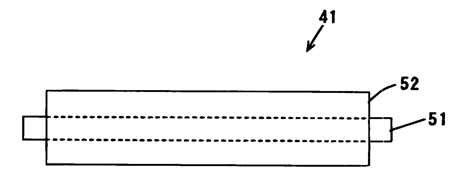
[0095]A third embodiment of the present invention will be explained next. In an experiment, Example No. 5 of the conductive foamed roller in the first embodiment was ground to have a specific outer diameter, thereby obtaining Example No. 30 of the conductive foamed roller.
[0096]First, similar to Examples No. 1 to No. 10, the first mold roller was obtained, and the first mold roller was placed in a convection oven at 130° C. for 3 hours in the second vulcanization process, similar to Example No. 5 shown in Table 3. After the conductive foamed rubber was integrated with the metal shaft portion, both end portions were cut, so that a total length of the rubber portion became 214 mm. Then, a surface of the rubber portion was ground, thereby obtaining a conductive foamed roller having a rubber thickness of 4.0 to 4.1 mm. Further, the conductive foamed roller had a drum shape having an outer diameter of 14.0 mm at both end portions thereof and an outer diameter of 14.1 mm at a center porti...
PUM
| Property | Measurement | Unit |
|---|---|---|
| compressive strain | aaaaa | aaaaa |
| compressive strain | aaaaa | aaaaa |
| volume resistivity | aaaaa | aaaaa |
Abstract
Description
Claims
Application Information