Angel wing abradable seal and sealing method

a technology of abradable sealing and angel wings, which is applied in the direction of machines/engines, stators, liquid fuel engines, etc., can solve the problems of severe rubbing, change of clearance, and decrepit efficiency of turbines

Active Publication Date: 2008-03-06
GENERAL ELECTRIC CO
View PDF22 Cites 37 Cited by
  • Summary
  • Abstract
  • Description
  • Claims
  • Application Information

AI Technical Summary

Problems solved by technology

If the clearance is too large, excessive valuable cooling air will leak through the gap between the bucket shank and the inner shroud of the stationary blade, decreasing the turbine's efficiency.
In this regard, it is known that there are clearance changes during periods of acceleration or deceleration due to changing centrifugal forces on the buckets, due to turbine rotor vibration, and due to relative thermal gro

Method used


Image

  • Angel wing abradable seal and sealing method
  • Angel wing abradable seal and sealing method
  • Angel wing abradable seal and sealing method

Examples


Embodiment Construction

[0011]Clearance control devices such as abradable seals have been proposed in the past to accommodate rotor to casing clearance changes. See for example U.S. Pat. Nos. 6,340,286, 6,457,552; and Published Application Nos. 2005-0003172, US 2005-0164027 and US 2005-0111967, the disclosure of each of which is incorporated herein by this reference. Such clearance control devices allow the designer to decrease the cold built clearance of the turbine or engine, which decreases unwanted leakage, thus improving the performance and / or efficiency of the turbine or engine.

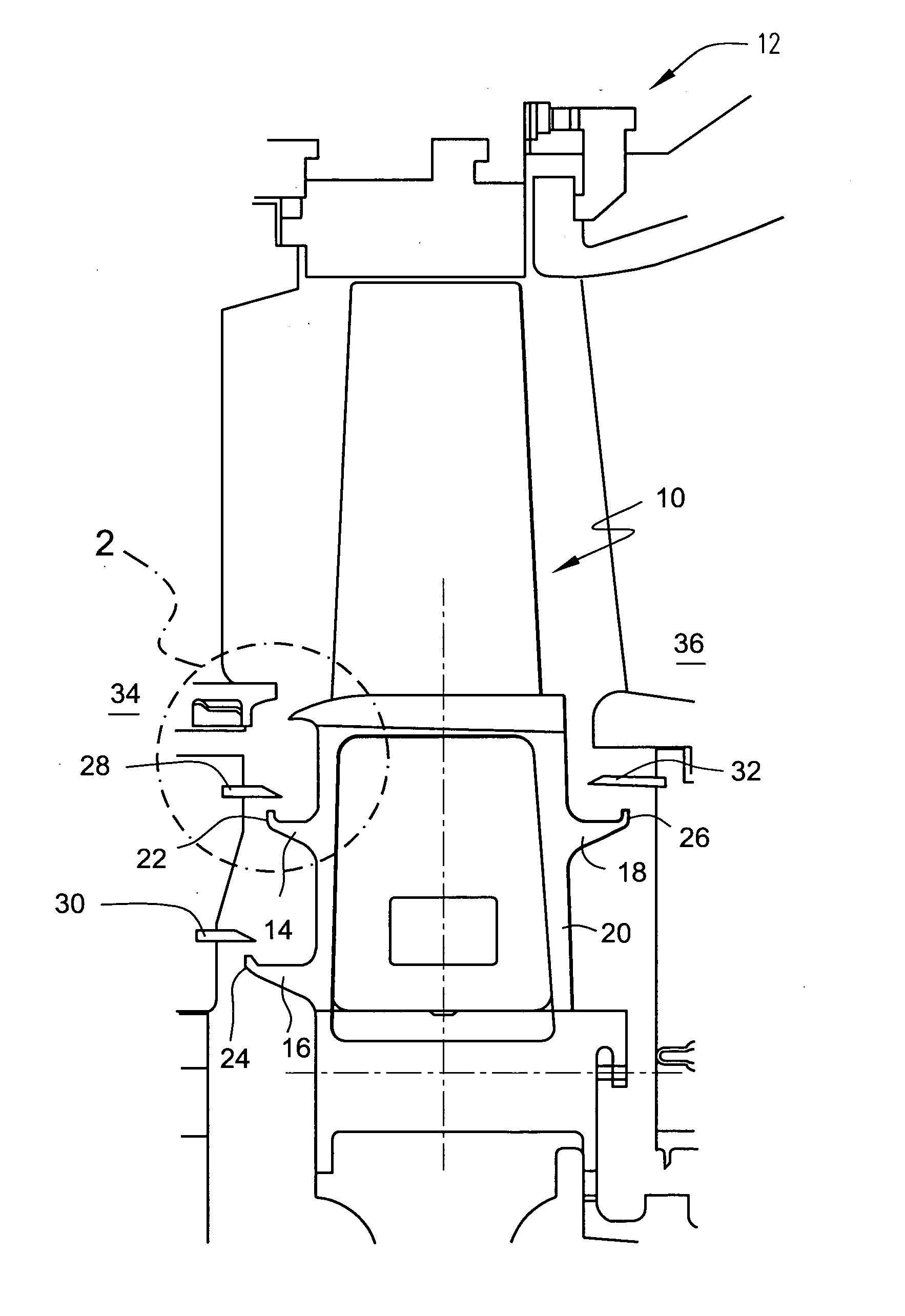
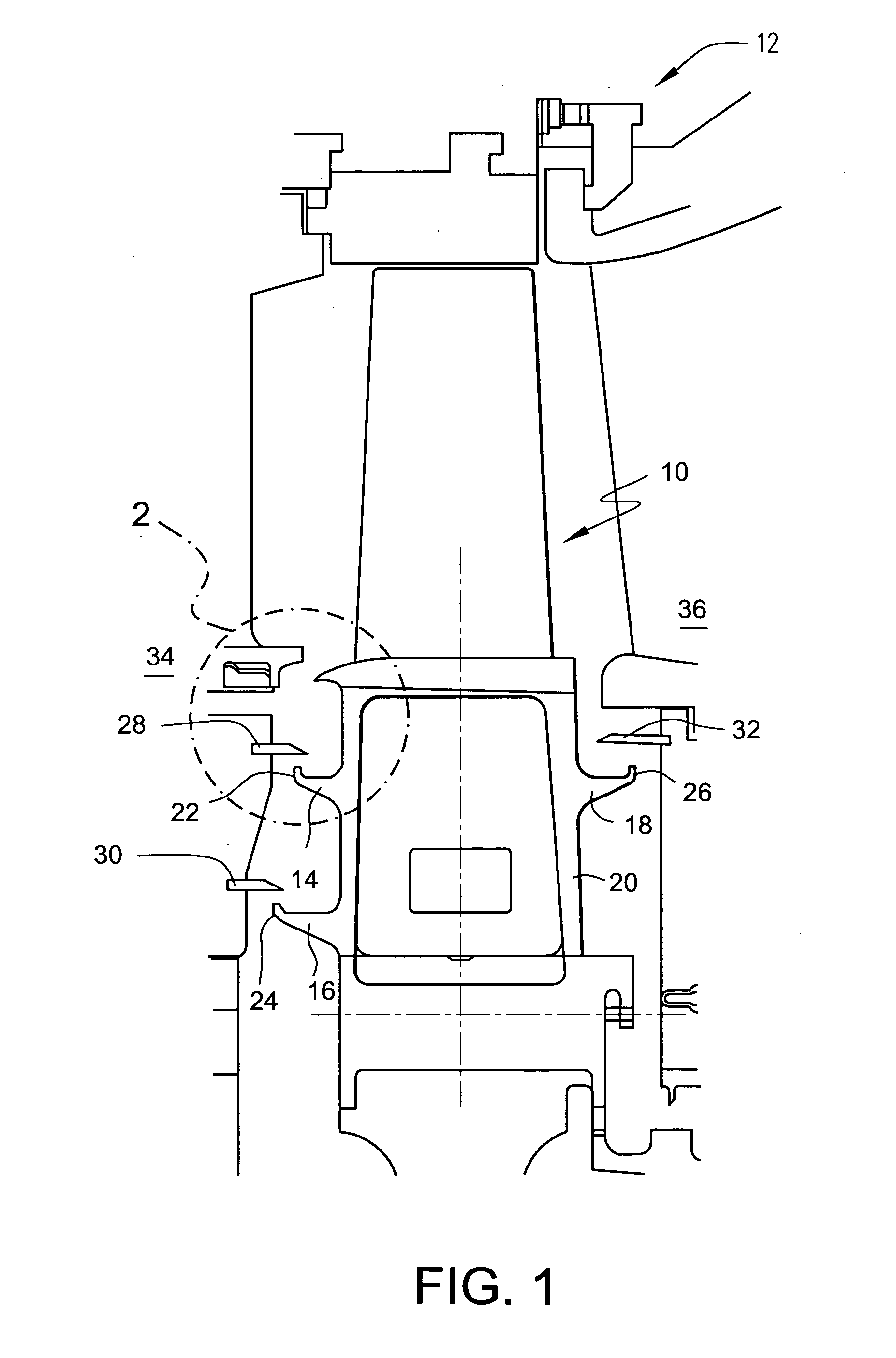
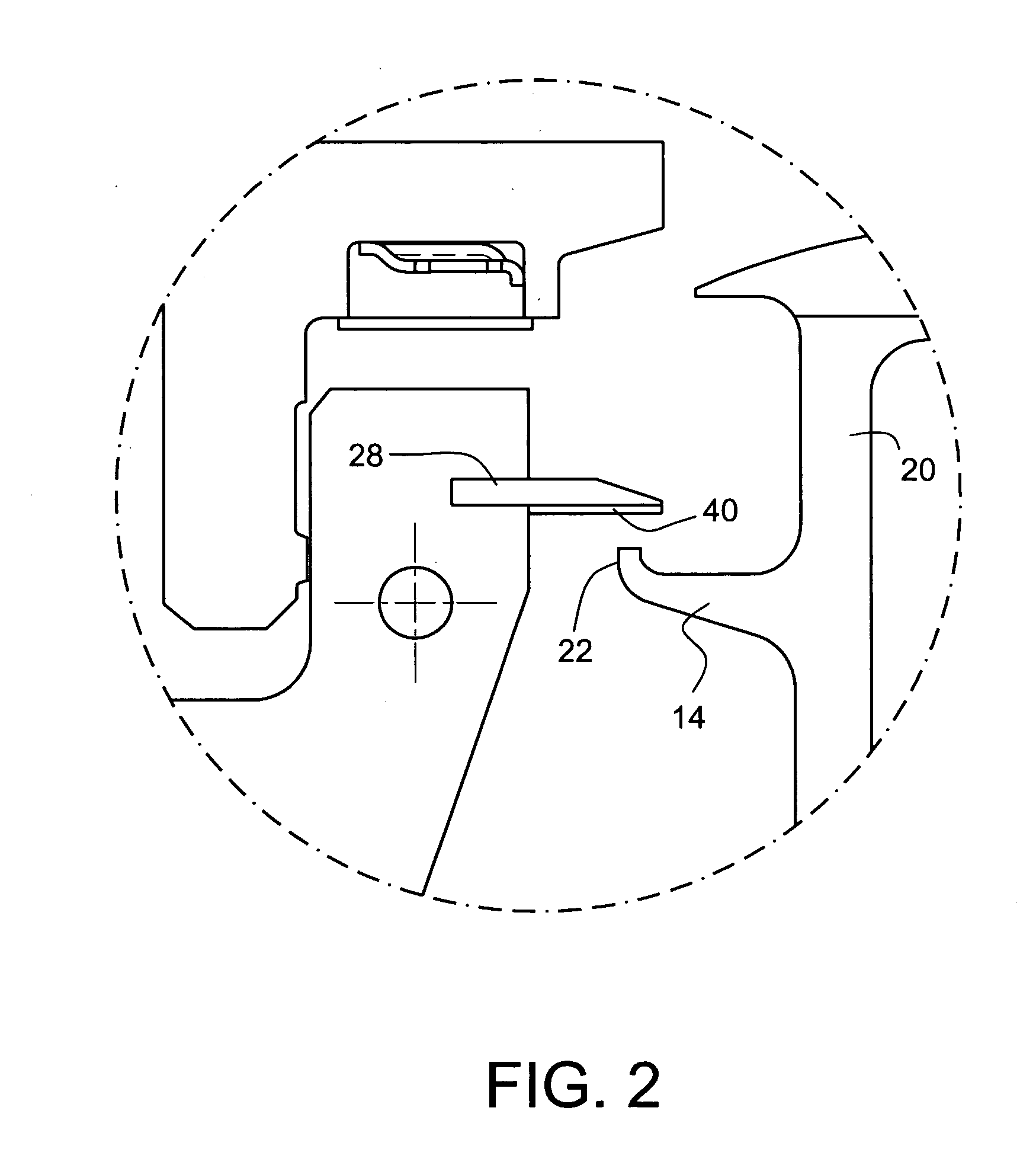
[0012]The invention relates generally to an abradable seal material provided at the interface between a stationary seal component and a rotating portion of the turbine. More particularly, the invention relates to an abradable seal material provided either on a seal gap facing surface of a flange projecting axially from a radially inner end portion of a stationary turbine blade or nozzle assembly, or on the opposed seal gap fac...


PUM


Abstract

An abradable seal is provided to improve turbine performance by physically reducing the clearance between a flange portion of the nozzle and an opposed angel wing/seal plate member of the bucket. The provision of an abradable seal also mitigates angel wing/seal plate tooth or fin wear by providing for abradable contact without metal to metal hard rub.

Description

BACKGROUND OF THE INVENTION[0001]The present invention generally relates to rotary machines such as steam and gas turbines and, more particularly, is concerned with a rotary machine having a seal assembly to control clearance between the shank portion of rotating rotor blades or “buckets” and a radially inner end of a stationary nozzle of the rotary machine.[0002]Steam and gas turbines are used, among other purposes, to power electric generators. Gas turbines are also used, among other purposes, to propel aircraft and ships. A steam turbine has a steam path which typically includes in serial-flow relation, a steam inlet, a turbine, and a steam outlet. A gas turbine has a gas path which typically includes, in serial-flow relation, an air intake or inlet, a compressor, a combustor, a turbine, and a gas outlet or exhaust nozzle. Compressor and turbine sections include at least one circumferential row of rotating buckets. The free ends or tips of the rotating buckets are surrounded by a...

Claims


Application Information

Patent Timeline
IPC IPC(8): F01D11/00
CPCF01D11/02F01D11/001F01D11/08F01D5/20F01D11/14
Inventor CHENG, YINGUOFANG, BIAOMCGOVERN, TARA EASTERWOLFE, CHRISTOPHER EDWARD
Owner GENERAL ELECTRIC CO
Why Eureka
Try Eureka