Pedometer
- Summary
- Abstract
- Description
- Claims
- Application Information
AI Technical Summary
Benefits of technology
Problems solved by technology
Method used
Image
Examples
first embodiment
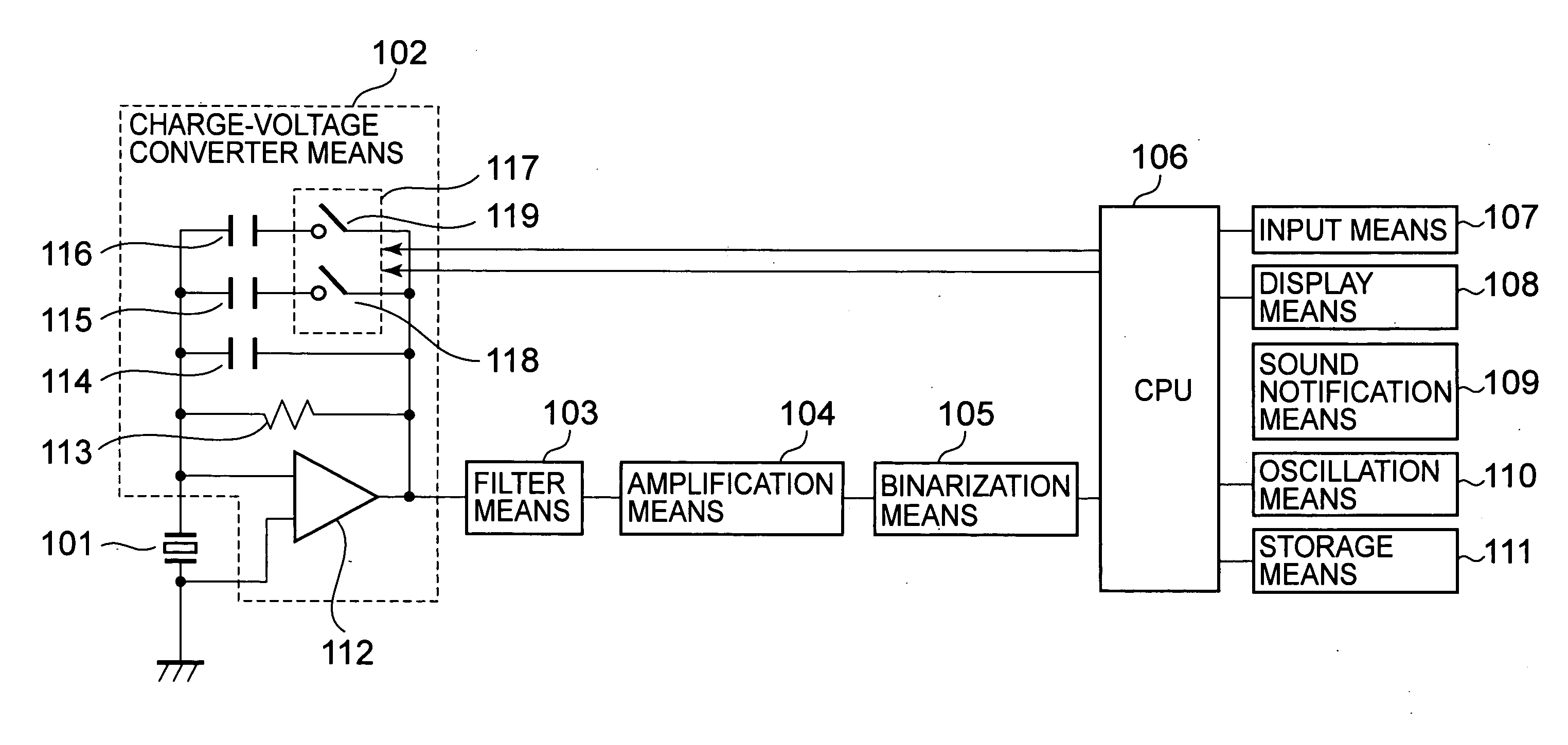
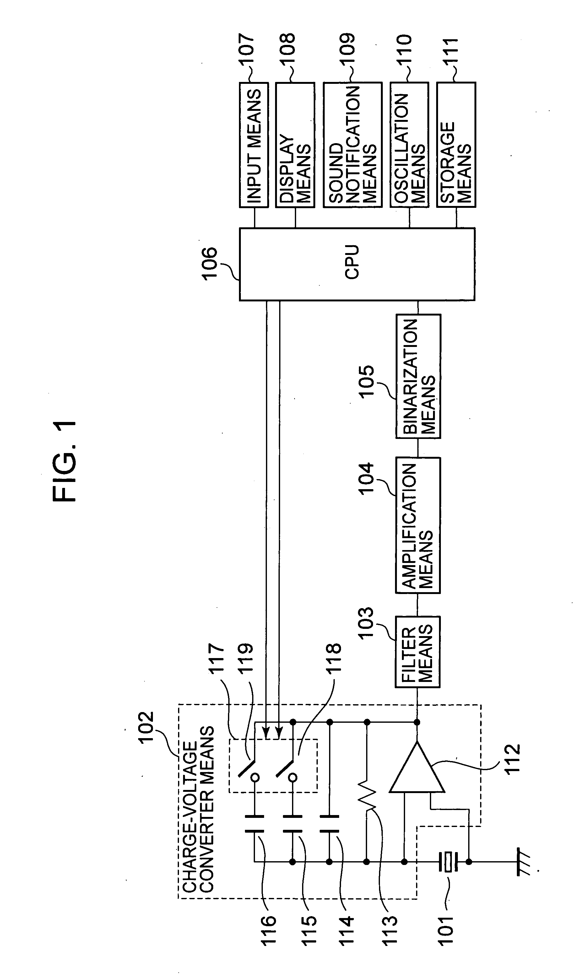
[0026]FIG. 1 is a block diagram of a pedometer according to the present invention, illustrating an example of a pedometer structured to be used by being carried in a state worn on the wrist or waste or put accommodated in a bag or the like.
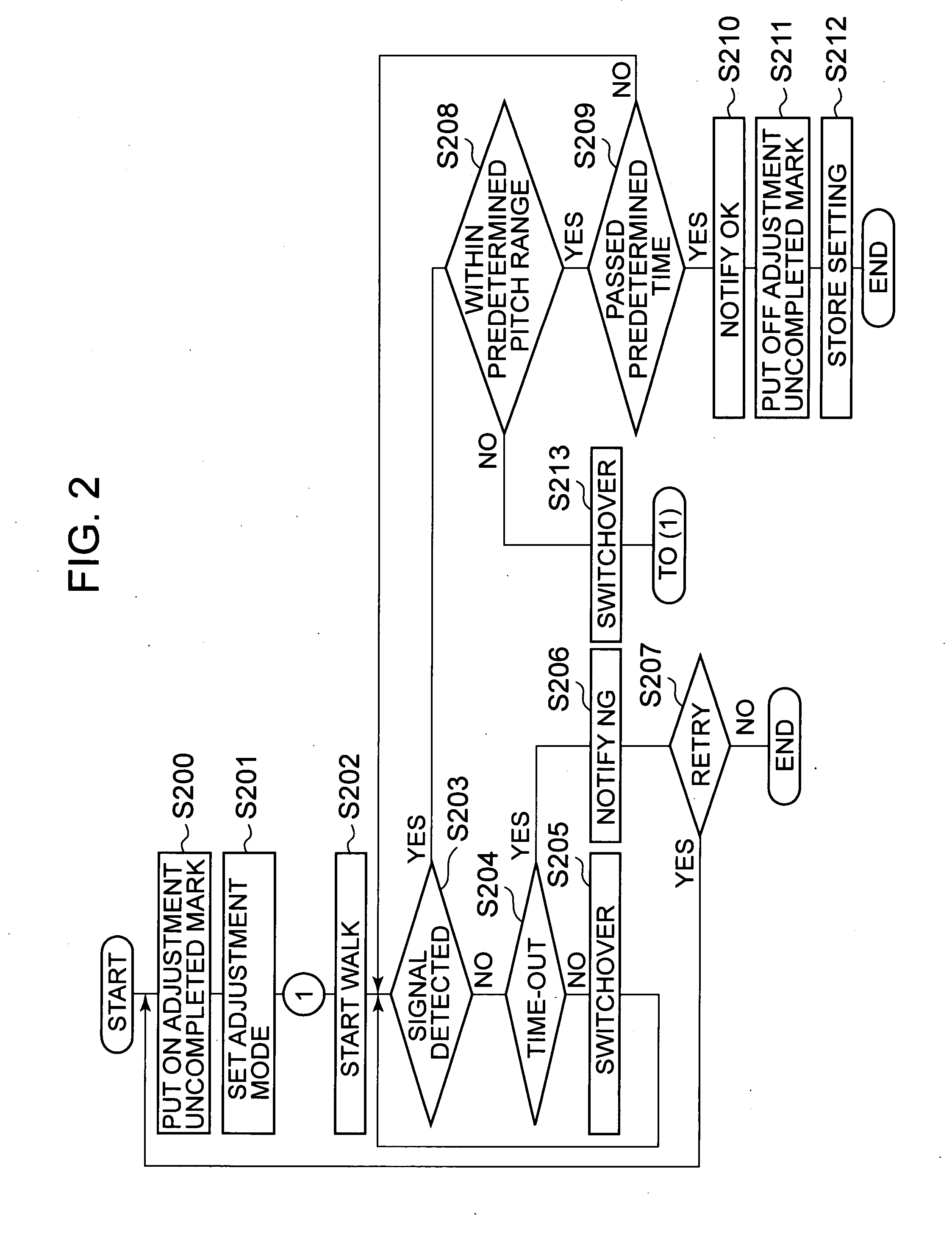
[0027]In FIG. 1, the pedometer has an acceleration sensor 101 that detects a walk (including a run) of the user and outputs a charge signal (walk signal) corresponding to the walk, charge-voltage converting means 102 that converts the charge walk signal of from the acceleration sensor 101 into the corresponding voltage walk signal to output, filter means 103 that outputs a walk signal removed of noise from the output signal of from the charge-voltage converting means 102, amplification means 104 that amplifies the walk signal of from the filter means 103 and outputs a walk signal in an analog form, and binarization means 105 that waveform-shapes the walk signal of from the amplification means 104 and outputs a walk signal in the form of a binary d...
second embodiment
[0065]FIG. 4 is a block diagram of a charge-voltage converting means for use on a pedometer according to the invention, wherein like reference numeral is attached to like element of FIG. 1.
[0066]In the second embodiment of the charge-voltage converting means 401, resistances 402, 403 for constituting an amplifier circuit are provided together with an operation amplifier 112, a resistance 113, etc. in the output of the operation amplifier 112. Due to this, the charge-voltage converting means 401 is configured having an amplifier circuit. Meanwhile, the capacitor circuit formed by capacitors 114-116 forms a feedback circuit for the amplifier circuit.
[0067]In response to the control signal from the CPU 106, the switch means 117 (switches 118, 119) are controlled to open and close thereby controlling the conversion gain.
[0068]By thus providing an amplifier circuit in the charge-voltage converting means 401, the conversion gain can be increased with a simple structure.
[0069]Meanwhile, ev...
third embodiment
[0070]FIG. 5 is a block diagram of a charge-voltage converting means for use on a pedometer according to the invention, wherein like reference numeral is attached to like element of FIG. 1.
[0071]The charge-voltage converting means 501 in the third embodiment is connected, in parallel, with a discharge resistance 502, a capacitor 503, conversion-gain control capacitors 504, 505 and switch means 506 (specifically, switches 507, 508) connected in series to the capacitors 504, 505, instead of using an operation amplifier.
[0072]In response to the control signal from the CPU 106, the switch means 506 (switches 507, 508) are controlled to open and close, thus controlling the conversion gain.
[0073]In this manner, because the charge-voltage converting means 501 is formed only by passive elements without using active elements such as an operation amplifier and the like, structure is available simple and at low cost.
[0074]Application is possible to various types of pedometers including a pedom...
PUM
 Abstract
Description
Claims
Application Information
 - R&D
- Intellectual Property
- Life Sciences
- Materials
- Tech Scout
- Unparalleled Data Quality
- Higher Quality Content
- 60% Fewer Hallucinations
Browse by: Latest US Patents, China's latest patents, Technical Efficacy Thesaurus, Application Domain, Technology Topic, Popular Technical Reports.
© 2025 PatSnap. All rights reserved.Legal|Privacy policy|Modern Slavery Act Transparency Statement|Sitemap|About US| Contact US: help@patsnap.com


