System and method for automating generation of an automated sensor network
- Summary
- Abstract
- Description
- Claims
- Application Information
AI Technical Summary
Benefits of technology
Problems solved by technology
Method used
Image

Examples
first embodiment
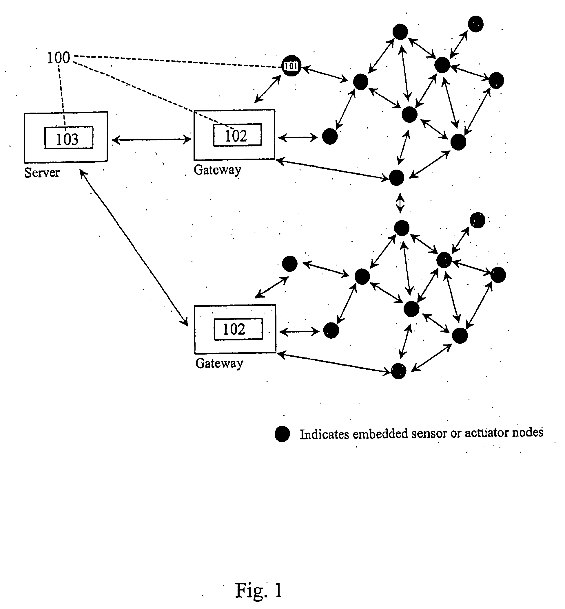
[0026] the invention is now described. FIG. 1 shows the conceptual diagram of a sensor or actuator network. The dark circles in the figure denote sensor or actuator nodes and the bi-directional arrows indicate bi-directional communication channels.
[0027] As can be seen from FIG. 1, the automatically generated executable application software 100 comprises three units: an executable software unit 101 resident on embedded sensor or actuator nodes, an executable software unit 102 resident on gateways which collect data from or control the operation of a plurality of said sensor nodes, and an executable software unit 103 resident on a server which collects data from or controls the operation of a plurality of said gateways.
[0028] The software unit 101 resides in the embedded sensor or actuator nodes and may, for example, perform functions such as: [0029] i) monitoring and control functions such as periodically or continuously monitoring sensor data, monitoring sensor data upon receipt o...
third embodiment
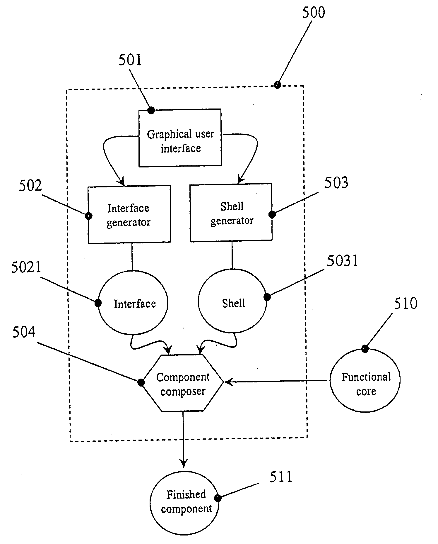
[0066] the present invention relates to the construction of the components themselves. As described earlier, a component consists of a functional core, an interface and a shell that provides information regarding the component. The functional core is typically programmed by a human to perform one or more logically related functions and unit tested to verify its operation. Once this human task has been completed, the task of componentizing this functional core can also be automated as described in this embodiment. Reference is made to FIG. 8 which shows the conceptual block diagram of a componentizer 500. The componentizer 500 comprises a graphical user interface 501, an interface generator 502, a shell generator 503 and a component composer 504.
[0067] The graphical user interface 501 allows a user to pick a functional core 510 through the means of, for example, choosing a source code file, choosing a pre-compiled object code file or choosing an intermediate bytecode object file to b...
PUM
 Abstract
Description
Claims
Application Information
 - Generate Ideas
- Intellectual Property
- Life Sciences
- Materials
- Tech Scout
- Unparalleled Data Quality
- Higher Quality Content
- 60% Fewer Hallucinations
Browse by: Latest US Patents, China's latest patents, Technical Efficacy Thesaurus, Application Domain, Technology Topic, Popular Technical Reports.
© 2025 PatSnap. All rights reserved.Legal|Privacy policy|Modern Slavery Act Transparency Statement|Sitemap|About US| Contact US: help@patsnap.com