Air-conditioning system for vehicle

a technology for air-conditioning systems and vehicles, which is applied in the direction of domestic cooling devices, lighting and heating devices, transportation and packaging, etc., can solve the problems of compartment temperature not being maintained at a level comfortable for vehicle occupants, the drive power consumed by the compressor is greatly increased, and the compartment temperature cannot be maintained at a comfortable level for vehicle occupants, etc., to achieve the effect of increasing vehicle acceleration performance and improving reliability

Inactive Publication Date: 2008-03-13
SANDEN CORP
View PDF18 Cites 4 Cited by
  • Summary
  • Abstract
  • Description
  • Claims
  • Application Information

AI Technical Summary

Benefits of technology

[0019]Preferably, the selection device should have control modes for controlling the acceleration-period cooling performance of the refrigeration circuit, where selection from the control modes is performed on the basis of a difference between pre-acceleration cooling performance of the refrigeration circuit at the acceleration start time and post-acceleration cooling performance of the refrigeration circuit estimated in consideration of vehicle acceleration. Specifically, the control modes can include a HOLD mode to be selected when the difference is within a specified range, that is, the difference is so small that it does not have a significant influence on the vehicle acceleration performance or the comfortable compartment temperature, for maintaining the acceleration-period cooling performance at the same level as the pre-acceleration cooling performance.
[0020]When the HOLD mode is selected, the acceleration-period cooling performance is maintained at the same level as the pre-acceleration cooling performance, so that the comfortable compartment temperature is maintained during the vehicle acceleration. Thus, the air-conditioning system has an improved reliability.
[0021]The control modes can include at least one of an UP mode and an DOWN mode to be selected when the difference is...

Problems solved by technology

When the compressor is driven to operate with the maximum refrigerant discharge capacity during acceleration of the vehicle, however, the drive power consumed by the compressor greatly increases with an increase in rotation speed of an engine equipped with the vehicle, which causes a great decreas...

Method used


Image

  • Air-conditioning system for vehicle
  • Air-conditioning system for vehicle
  • Air-conditioning system for vehicle

Examples


Embodiment Construction

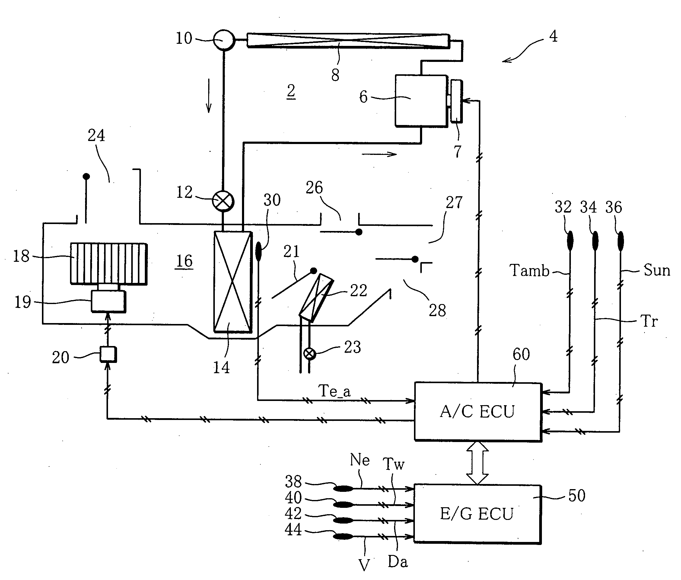
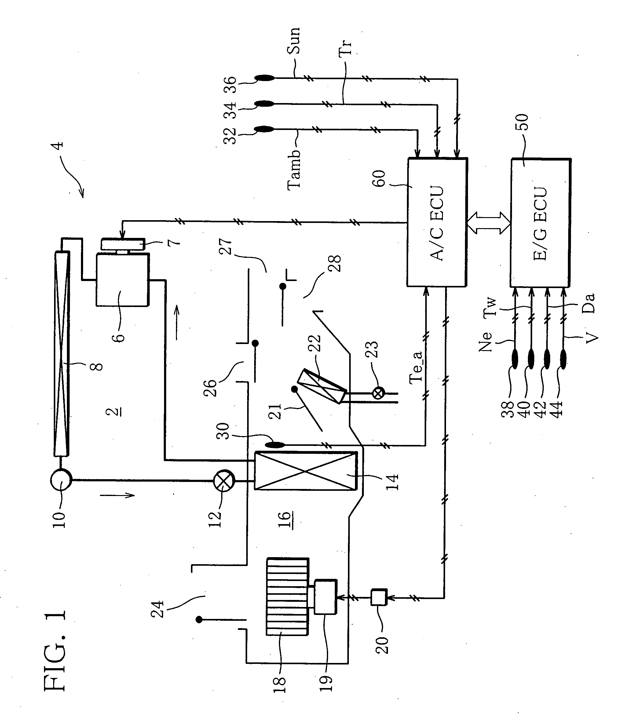
[0046]FIG. 1 schematically shows a part including an engine room 2. A vehicle is provided with an air-conditioning system, and this system comprises a refrigeration circuit 4. The refrigeration circuit 4 has a refrigerant circulation path, and by a refrigerant circulating along the circulation path, the temperature of the vehicle interior is regulated to within a range set as desired.

[0047]Specifically, in the circulation path, a variable capacity compressor 6, a condenser 8, a liquid receiver, also called simply a receiver 10, an expansion valve (expansion mechanism) 12 and an evaporator 14 are disposed in this order. The compressor 6, condenser 8, receiver 10 and expansion valve 12 are arranged in the engine room 2, while the evaporator 14 is located within a ventilation duct 16. The ventilation duct 16 is arranged behind the engine room 2.

[0048]In the present embodiment, the compressor 6 is driven by an engine (not shown) of the vehicle. Specifically, the compressor 6 includes an...


PUM


Abstract

An air-conditioning system for a vehicle according to the present invention has an ECU which executes a control routine for controlling the cooling performance of a refrigeration circuit during vehicle acceleration. The control routine includes the steps of detecting demanded vehicle-acceleration degree, detecting evaporator exit air temperature at the time vehicle acceleration starts, selecting acceleration-period cooling performance on the basis of the demanded acceleration degree and the exit air temperature, and outputting a capacity control signal to a compressor on the basis of the acceleration-period cooling performance selected.

Description

BACKGROUND OF THE INVENTION[0001]1. Field of the Invention[0002]This invention relates to an air-conditioning system for a vehicle, specifically, an air-conditioning system comprising a variable capacity compressor.[0003]2. Description of the Related Art[0004]A variable capacity compressor provided in an air-conditioning system for a vehicle can regulate the cooling performance of the air-conditioning system, or in other words, the cooling performance of the refrigeration circuit thereof by its refrigerant discharge capacity being varied. Specifically, under the conditions such that the thermal load in a passenger compartment of the vehicle is high, as in summer, the compressor is driven to operate with a maximum refrigerant discharge capacity. This causes a drop in the temperature of conditioned air blown out into the compartment so that the compartment temperature is regulated to a level comfortable to the vehicle occupant.[0005]When the compressor is driven to operate with the ma...

Claims


Application Information

Patent Timeline
IPC IPC(8): F25B1/00
CPCB60H1/3208B60H2001/3275B60H2001/3266B60H2001/3261
Inventor IMAI, TOMONORI
Owner SANDEN CORP
Why Eureka
Try Eureka