Cooling system for hybrid power system

a hybrid power system and cooling system technology, applied in the direction of machines/engines, battery/fuel cell control arrangements, electric devices, etc., can solve problems such as the need for cooling hybrid power system components

Active Publication Date: 2008-03-13
CUMMINS POWER GENERATION
View PDF21 Cites 39 Cited by
  • Summary
  • Abstract
  • Description
  • Claims
  • Application Information

AI Technical Summary

Problems solved by technology

When utilizing such a hybrid power system onboard a vehicle, proble...

Method used


Image

  • Cooling system for hybrid power system
  • Cooling system for hybrid power system
  • Cooling system for hybrid power system

Examples


Embodiment Construction

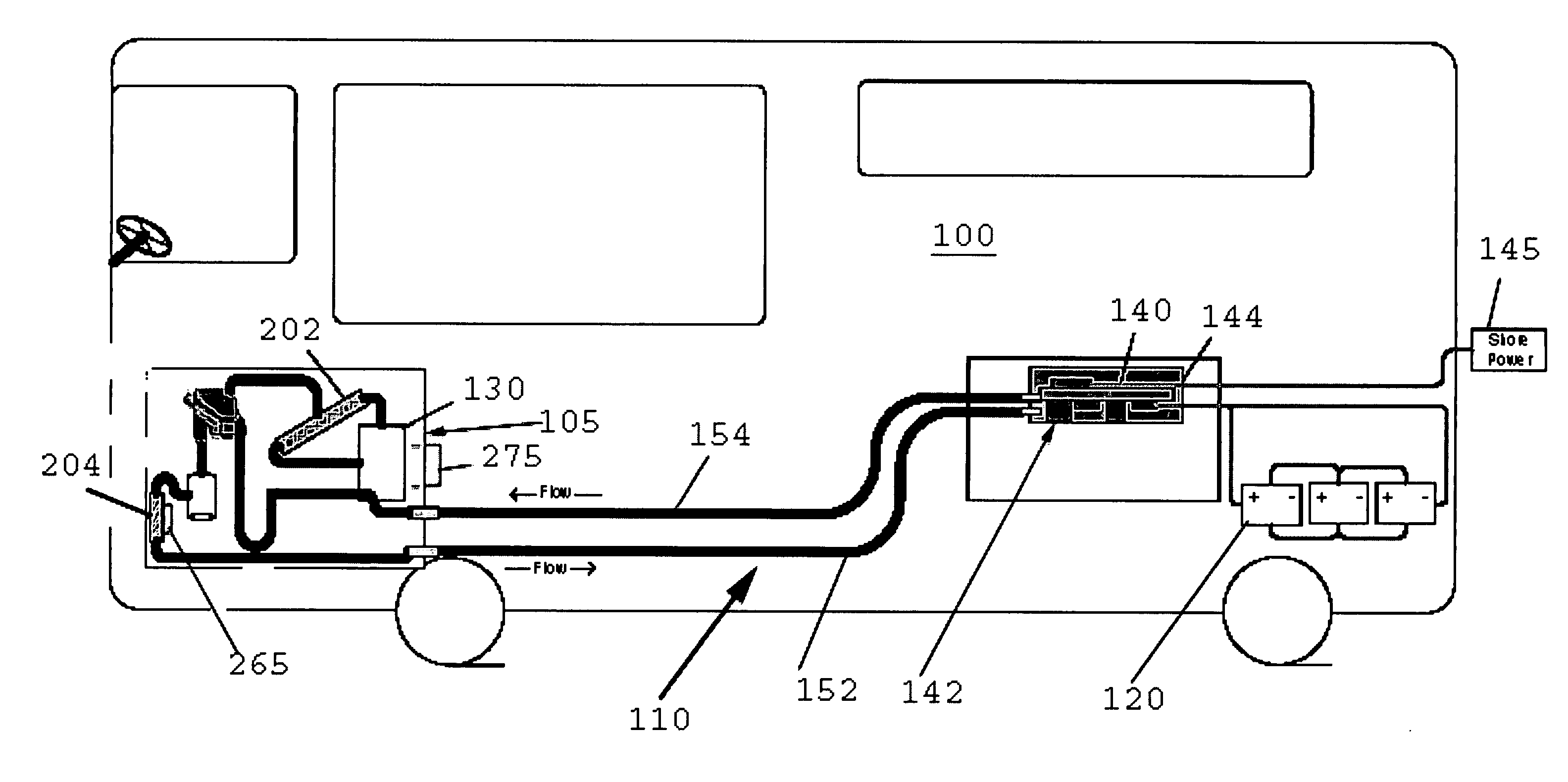
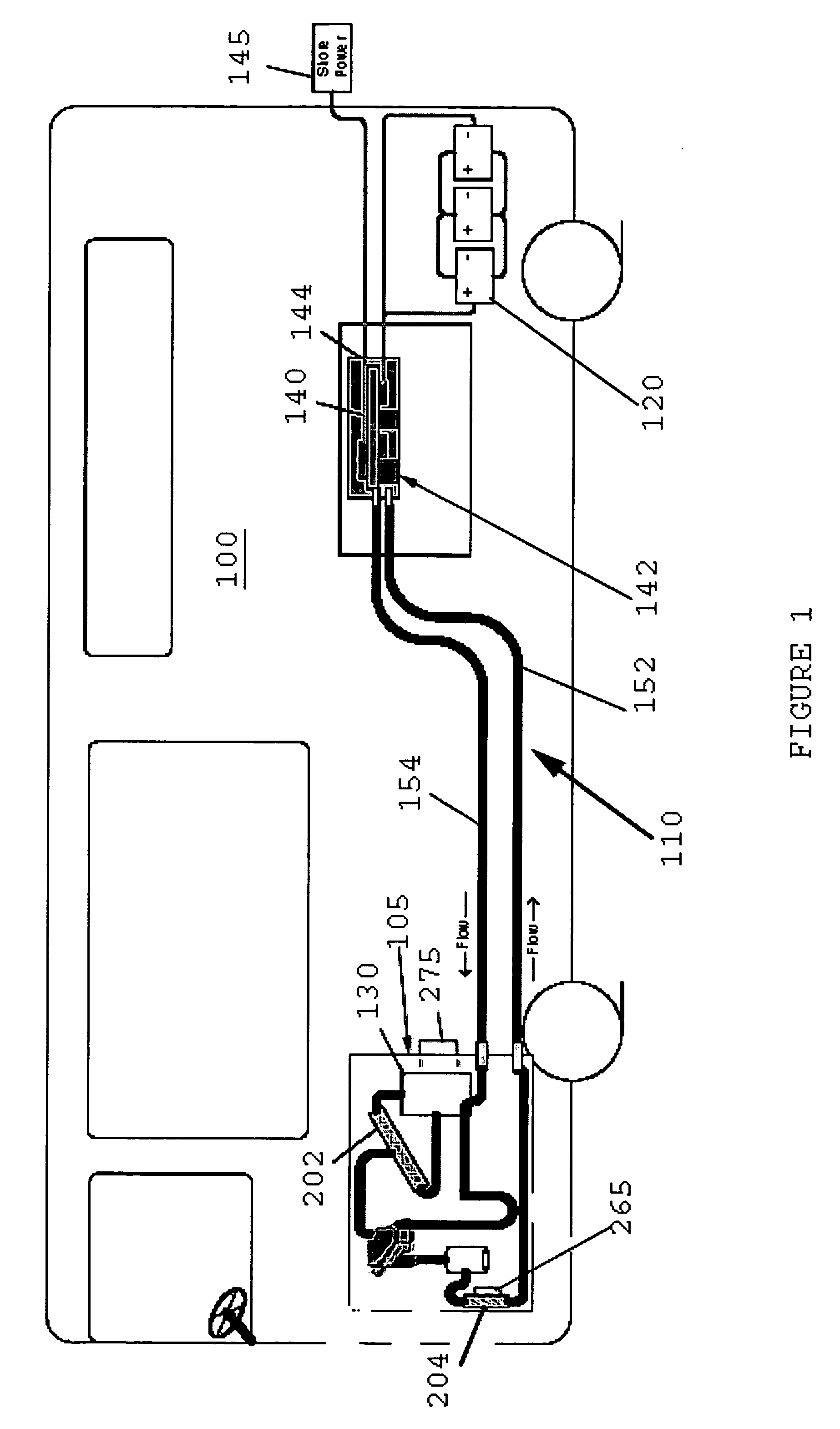
[0012]FIG. 1 is a schematic representation of a hybrid power system including a cooling system 110 for the hybrid power system, in accordance with one embodiment. Cooling system 110 is shown embodied within in a recreational vehicle (RV) 100. Other embodiments can utilize cooling system 110 in other types of vehicles, such as, but not limited to, various types of aircraft or watercraft. A vehicular hybrid power generation system generally includes an electrical generator unit 105 including a generator engine 130, a battery bank 120, and a power conversion device such as, but not limited to, an inverter 140. The hybrid power system can also be seen to include an input for shore power 145. These components are operatively coupled to a controller 142 which manages the power requirements of RV 100.

[0013]In one embodiment, generator engine 130 can include a variable speed engine. Generator engine 130 receives fuel such as diesel, natural gas or liquid propane vapor through an intake. Gen...


PUM


Abstract

A cooling system for a hybrid power system that includes an engine employs an engine cooling circuit to deliver coolant to the engine, the engine cooling circuit including a radiator and a main fan to draw air through the radiator. When the hybrid power system further includes an inverter, then the inverter is cooled via an inverter cooling circuit that is formulated as one portion of the cooling system to deliver coolant to the inverter, the inverter cooling circuit including a heat exchanger located such that the main fan draws air through the heat exchanger when the main fan is active. The cooling system also includes a secondary fan to selectively draw air though the heat exchanger during operation of an inverter cooling circuit coolant pump.

Description

BACKGROUND OF THE INVENTION[0001]1. Field of the Invention[0002]This invention relates to the field of power generating systems, and more specifically to a cooling system for a vehicular hybrid power system.[0003]2. Description of the Prior Art[0004]A typical vehicular hybrid power system utilizes both a battery stack and a generator engine unit to develop electrical power. The battery stack can typically be charged from either the generator engine unit or from shore power. The hybrid power system can be used, for example, to generate electrical power for a vehicle such as a recreational vehicle (RV). When utilizing such a hybrid power system onboard a vehicle, problems can arise with the need for cooling the hybrid power system components. Manufacturing costs, maintenance costs, and space requirements are only some of the factors that need to be optimized for such a system.SUMMARY OF THE INVENTION[0005]A vehicular hybrid power system generally includes an engine driven electrical p...

Claims


Application Information

Patent Timeline
IPC IPC(8): F01P1/06
CPCB60K11/02Y02T10/7241B60K2001/005B60L11/1874B60L2240/525B60W10/30B60W20/00F01P1/06F01P2005/046F01P2050/24Y02T10/70Y02T10/7005Y02T10/705B60L1/003B60L3/003B60L11/14B60L11/1877B60L2200/18B60L2210/40B60L2240/36B60L2240/445B60L2240/529B60L2240/527Y02T10/7077B60K2001/003B60H1/00364B60L50/16B60L58/26B60L50/66B60H2001/00307Y02T10/72Y02T10/7072B60W2300/10
Inventor CARNEY, ALLEN B.HUGHES, JOHN C.KEENE, KEVIN J.KLINKERT, DEBORAH A.PADGET, BRADLEY D.
Owner CUMMINS POWER GENERATION
Why Eureka
Try Eureka