Oil filter mounting structure in internal combustion engine

a technology for mounting structures and oil filters, which is applied in the direction of lubricant mounting/connection, lubrication elements, pressure lubrication, etc., can solve the problems of not being protected from stones hitting the oil filter, being subject to disturbance, etc., and achieves simple configuration, reduced oil total, and reliable protection from stones

Inactive Publication Date: 2008-03-13
HONDA MOTOR CO LTD
View PDF3 Cites 19 Cited by
  • Summary
  • Abstract
  • Description
  • Claims
  • Application Information

AI Technical Summary

Benefits of technology

[0019]Since the oil filter mounted on the oil filter mounting surface of the spacer interposed between the crankcase and the case cover is arranged in the recess of the crankcase opening on top, the oil filter is reliably protected from stones or the like from below.
[0020]Since the spacer is formed with the lubrication system, the filter introducing channel of oil from the oil pump to the oil filter mounted on the spacer and the filter deriving channel extending from the oil filter to the respective parts to be lubricated or the like are shortened, the total amount of the oil may be reduced, and the crankcase itself is downsized, so that the compact light-weight internal combustion engine is achieved.
[0021]Since the spacer is assembled with the oil pump and is formed with the filter introducing channel and the filter deriving channel formed at least into a recess in cross section, the oil pump and the oil filter may be arranged intensively on the spacer. Therefore, short oil channels may be formed with a simple configuration, and it is not necessary to form complicated oil channels in the crankcase, whereby the crankcase itself may further be downsized.
[0022]Since the partitioning plate is brought into abutment with the opening end surface of the opposed channel walls which is in flush with the mating surface with respect to the case cover to configure the filter introducing channel and the filter deriving channel, the filter introducing channel and the filter deriving channel may be configured easily with a small number of parts. As a result, the weight of the engine and the labor required to assemble the engine can be reduced.
[0023]Since the oil tank chamber is formed between the side wall of the spacer which is close to the mating surface with respect to the crankcase and the case cover, the oil tank chamber swells toward the crankcase. Hence, a large capacity of the oil tank chamber may be secured with a simple configuration in which the lubrication system such as the pump body is formed on the spacer.
[0024]The pump intake channel formed in the pump body of the spacer has the pump intake port opening at the lower portion of the oil tank chamber, and the pump body and the pump intake port are formed integrally. Thus, the oil pump configuration is simple.

Problems solved by technology

Therefore, in a vehicle-mounted internal combustion engine, the oil filter mounted to the crankcase so as to protrude therefrom is subject to disturbance during travel.
Therefore, the oil filter provided in the curved recess is protected from stones coming from the front, but is not protected from stones hitting thereto from below.

Method used


Image

  • Oil filter mounting structure in internal combustion engine
  • Oil filter mounting structure in internal combustion engine
  • Oil filter mounting structure in internal combustion engine

Examples


Embodiment Construction

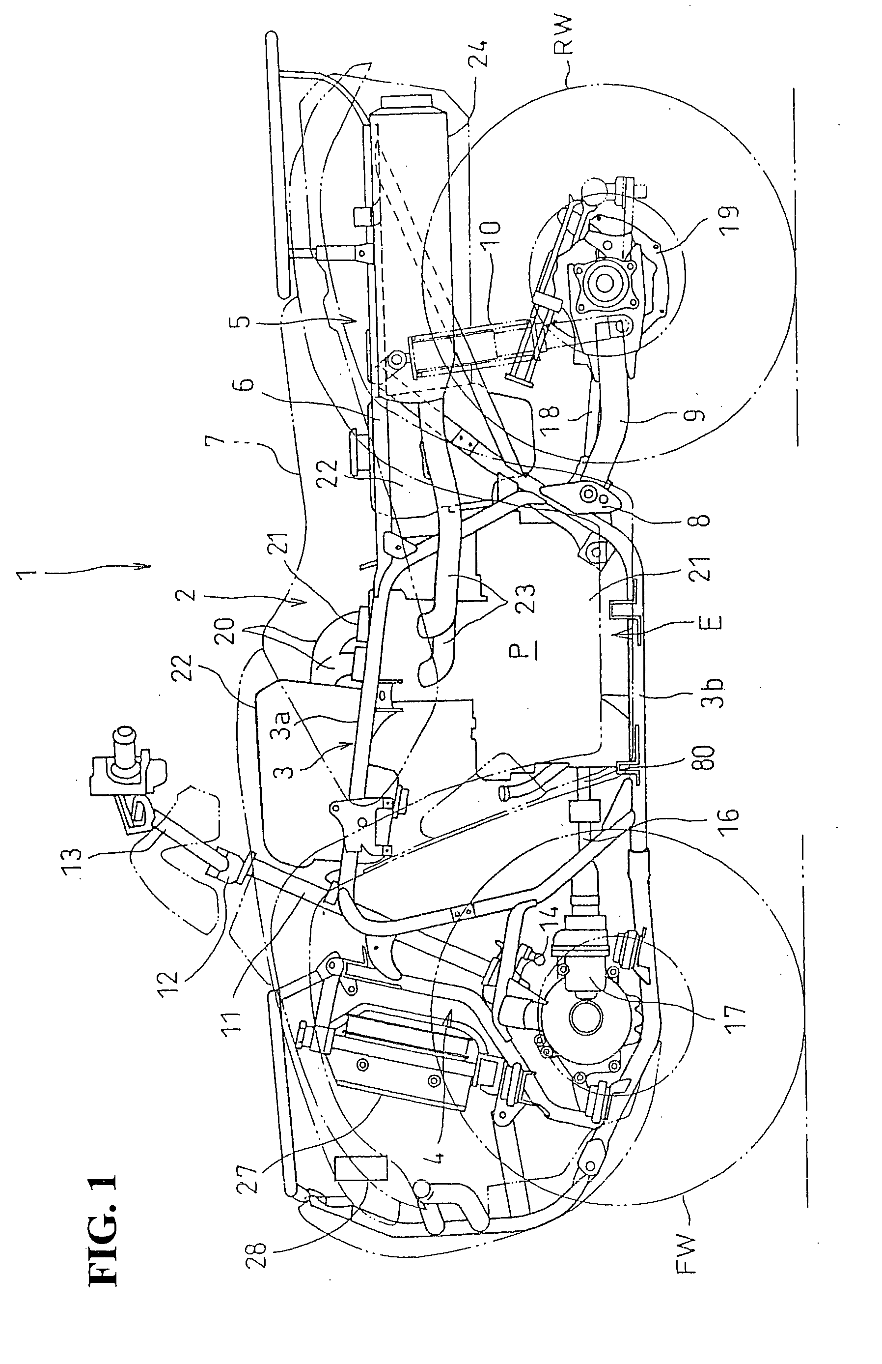
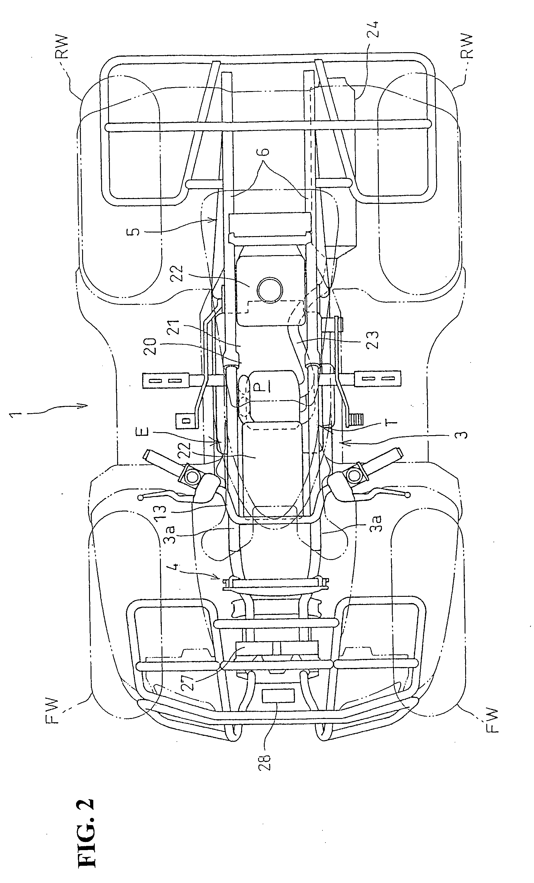
[0041]A side view of a rough-terrain traveling vehicle 1 in which a water-cooled internal combustion engine E according to this embodiment is mounted with a vehicle body cover or the like removed is shown in FIG. 1, and a plan view of the same is shown in FIG. 2.

[0042]In this embodiment, the front, rear, left and right are defined on the basis of a direction viewing in the direction of travel of the vehicle.

[0043]The rough-terrain traveling vehicle 1 is a saddle type four-wheel vehicle, and a pair of left and right front wheels FW on which low-pressure balloon tires for rough-terrain are mounted and a pair of left and right rear wheels RW on which the same balloon tires are mounted are suspended in the front and rear of a vehicle body frame 2.

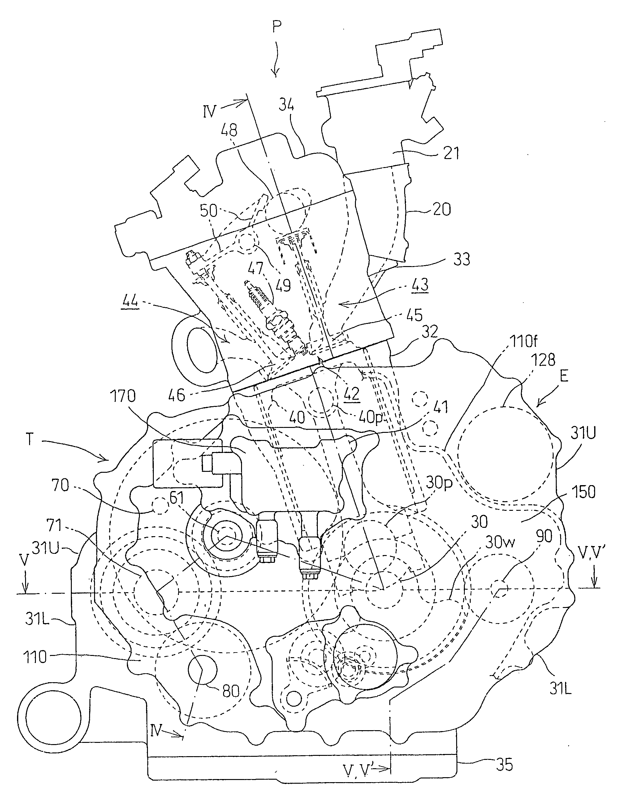
[0044]The vehicle body frame 2 is configured with a plurality of types of steel material joined together, and includes a center frame portion 3 in which a power unit P having the internal combustion engine E and a transmission T provided integr...


PUM


Abstract

An oil filter mounting structure in an internal combustion engine in which the outside a crankcase in the direction of a crankshaft is covered by a case cover. A spacer is interposed between the crankcase and the case cover. The spacer is formed with a lubrication system. An oil filter is mounted to an oil filter mounting surface of the spacer which is flush with a mating surface with respect to the crankcase. A part of the crankcase to which the oil filter mounting surface of the spacer faces is formed with a recess opening on top to which the oil filter is mounted. The resulting configuration provides an oil filter mounting structure in which an oil filter is reliably protected from stones. Further, oil channels are shortened to achieve a compact light-weight internal combustion engine.

Description

CROSS-REFERENCE TO RELATED APPLICATION[0001]The present application claims priority under 35 U.S.C. §119 to Japanese Patent Application No. 2006-246098, filed Sep. 11, 2006, the entire contents of which are hereby incorporated by reference.BACKGROUND OF THE INVENTION[0002]1. Field of the Invention[0003]The present invention relates to an oil filter mounting structure in an internal combustion engine.[0004]2. Description of Background Art[0005]A lubrication system in an internal combustion engine is generally configured in such a manner that oil accumulated in an oil pan is pumped by an oil pump, and the oil discharged from the oil pump is supplied to the respective parts to be lubricated in the internal combustion engine.[0006]The oil discharged from the oil pump passes through an oil filter before being supplied to the respective parts to be lubricated so that impurities are eliminated from the oil.[0007]The oil filter is mounted to a crankcase in which oil channels are configured ...

Claims


Application Information

Patent Timeline
Patent Type & Authority Applications(United States)
IPC IPC(8): F01M11/03
CPCF01M11/02F02B61/02F01M11/03
Inventor INUI, HIROATSUSUMI, HIROMIBABA, TOMOKAZUTAWARA, HIDEYUKI
Owner HONDA MOTOR CO LTD
Why Eureka
Try Eureka